 This
mod will increase the output level with the expense of a little distortion.
This
mod will increase the output level with the expense of a little distortion.
Copyright 2003 by Aron Nelson, All Rights Reserved.
Please do not copy these mods and post them on your site. Please link to this document instead.
Increasing gain using diodes
If you have a circuit like the Jordan Bosstone or MXR Distortion+ or DOD overdrive 250 and others that have a diode pair creating the distortion at the end of a circuit, you can increase the output level of the circuit with the expense of a little distortion by putting two diodes where there were one. So instead of 2 diodes, you now have four.
This
mod will increase the output level with the expense of a little distortion.
More diodes in series will also give you a wider range of clean to distorted sound but less distortion when the circuit is maxxed. Something to note is that a germanium diode "clips"at around .3V and a silicon diode "clips" around .6V so you need roughly 2 germanium diodes to equal one silicon diode. A good multimeter will allow you to measure the diode and find out what the forward voltage is. LEDs will clip even later and give you more range of clean to distortion.
Buzzwords: "Touch sensitivity increase", "More feel", "increased gain", "more dynamic range", "less compressed".
Mellowing out distortion using a capacitor around diodes
You can put a capacitor in parallel around the 2 diode pair and mellow out the high end of the distortion. Increasing the capacitor value will cut out more and more of the highs.
 Changing
the capacitor value will alter how much highs get cut from the distortion. Start
with 100pf and start working up. Try 250pf, then 470pf etc..
Changing
the capacitor value will alter how much highs get cut from the distortion. Start
with 100pf and start working up. Try 250pf, then 470pf etc..
Buzzwords: "Smooth out", "focus"
Asymmetrical Distortion with diodes
In the diode pair, make one diode germanium and another silicon. Alternately, put two diodes on one side and one on the other.
Essentially mismatch diodes to get this. Use a multi-meter that can measure diodes to find mismatches. Apparently some people feel this will give a more "tube-like" distortion. This is useful in both diodes to ground as shown above as well as diodes in a feedback loop like the Tube Screamer.
Buzzwords: "Tube-like mod", "Asymmetrical distortion", "Tube overdrive distortion"
Increasing bass response in and out of distortion box
If the box has a small value input or output capacitor like.01uF, you can change the capacitor to a larger value such as.1uF and this will feed the unit more bass. If you change the input capacitor to a larger value, you will put more bass into the distortion circuit. If you change the output capacitor to a larger value, you will output more bass after the distortion.
Buzzwords: "Fatten", "Thicker"
Decreasing bass response in and out of the distortion box
To decrease the bass response going into the clipping part of a pedal, decrease the input capacitor's value. Usually anything smaller than .01uF will start cutting off bass. If you change the output capacitor to a smaller value, you will have the same type of clipping but will reduce the bass response at the end of the circuit. Basically a high pass filter at the end of the pedal. If you make the input capacitor very small i.e. .005uF etc... you will basically make any pedal that boosts into a treble booster!
Buzzwords: "Thin out", "Tighten"
Change the capacitor material type
A cumulative change you can make is to replace most ceramic capacitors with their film equivalents. Unfortunately film caps are usually larger than ceramics so this mainly applies to when you are going to build your own pedals or modify existing ones where space permits. Subjectively, the different between ceramic and film is an overall "smoother" sound. If you want more "grit" to your tone, try replacing film caps with their ceramic equivalents. Some people feel that cheap ceramics sound more "open" and better for distortion pedals, try these cheap ceramics and see if you can hear the difference. Try them in tone control circuits and other critical areas. Some of my best pedals used cheapo ceramics. You can also try combinations of capacitors. Take two capacitors half the value of the desired combination and make one a ceramic and the other a film to get a different tone. For example, for a .1uF cap, try .047uF ceramic and .047uF film in parallel to get a .1uF "combo" cap.
Buzzwords: Film Caps = "Hi Fi", "Studio Quality", "Hi Grade"
Adding a "softness" or clipping threshold control
You can put a pot in series between the signal and diode pair to adjust the clipping threshold of the diodes. This acts like a "softness" control. I saw this described by R.G.Keen.
 This
works well. You can also put the bounding resistor between the diodes and ground.
This
works well. You can also put the bounding resistor between the diodes and ground.
Change the diode type
Change the clipping diodes to different types to get different "shades" of distortion. LEDs give more crunch and buzz. Silicon diodes (1N4148, 1N914) are crisper (harsher?) than germanium (1N34a). Germanium (Ge), Silicon (Si), FETs and MOSFET transistors also have diodes in them that you can use as clippers. Try different types in your circuit.
Buzzwords: Ge = "squishy", "tubey", "compressed".
Si = "sharp", "focused","tight", "precise"
FETs/MOSFETs = "Tube-like", "Crunchy"
LEDs = "Crunch", "Buzz", "Less Compressed"
Quick and easy transistor changes
You can install transistor sockets in your stompbox so thatyou can mix and match transistors easily. Mouser is one place that carries them (Part No: 151-TO-18320G). Use the hFE function on your multimeter to mix and match different transistors with different gains and hear the difference.
You can also order sockets from Small Bear Electronics.Add a bias pot
One way to make your distortion a little more versatile is to add a bias pot. You can put a trimmer pot (sold at Radio Shack etc...) in place of any one of the bias resistors (for example on the differential distortion, no drive or bias pot is on the circuit. You can make one by replacing a bias resistor with a trimmer pot or regular pot. Any pot with a value at least as large as the original resistor value will do. Additionally, put a small value resistor in series with the replacement pot for safety. To use a pot as a variable resistor, tie one of the outer lugs to the wiper (middle lug). Now connect the middle lug to one end of where the resistor was and the other unused lug to the other remaining resistor connection.

Add a lowpass filter
A lot of distortions don't have tone controls. Here is an easy lowpass filter you can add. It will reduce your output a little but if your distortion pedal has lots of gain, this shouldn't be a big problem. If you think about it, this can go right on the lugs of the output volume pot. Use a small trimmer mounted on the lugs of the output pot along with the capacitor.
Getting more distortion out of an IC-based distorter such as a Tube Screamer
 excerpt
from Jack Orman's Son of Screamer
excerpt
from Jack Orman's Son of Screamer
You can increase the value of the drive pot for a quick and easy mod that will give you more drive=distortion. If the pedal has two or more diodes in series, you can remove one of them to squash the signal down even more. You can also change the diodes to a different type for different "flavors" of distortion. You can also change the .05 capacitor that connects to Vr to .1uF or higher for more bass response out of the unit. To make a TS series circuit brighter, remove C4 (the .22uF to ground after the 1K resistor), this will brighten up the circuit. Another mod you could do is simply reduce the value of the 4.7K resistor R2 and this will increase the gain of the circuit. In order to keep the same frequency response, you will have to play with the value of C2.
Buzzwords: "Extended gain", "more distortion", "more transparent"
Add a low cut filter
Here's an interesting one to try, put a low cut if your distortion has too much bass. Put this at the end of a gain stage or at the end of the circuit.
 The
pot value is 500K.
The
pot value is 500K.
Create a band pass filter
A lowpass filter followed by a low cut filter will create a band pass filter if the lowpass frequency is higher than the low cut frequency. Changing the values of the capacitors will let different frequencies through.
Variation on lowpass filter
 Make
the first capacitor one value (for example: .01uF), the second capacitor another
(.05uF). Make the pot fairly large ~500K. When the pot is centered, very little
tone control is applied. This would go at the end of a circuit or even in the
middle of two gain stages.
Make
the first capacitor one value (for example: .01uF), the second capacitor another
(.05uF). Make the pot fairly large ~500K. When the pot is centered, very little
tone control is applied. This would go at the end of a circuit or even in the
middle of two gain stages.
Big Muff Tone Circuit
I have had good success splicing this tone control in my pedals. This tone circuit goes right before the volume control.
To design your own Big Muff filter, check out Duncan's Tone Stack Calculator.
BTW: the Big Muff tone control can be used to create a really scooped mids tone. Play with the Duncan Tone Stack Calculator to see what can be done.
Testing EQ changes
A great tip provided by R.G. Keen is to put a 5 band graphic EQ in front of your distortion and another at the end. The one in front can be used to gauge how changes to the input cap will affect the tone of the distortion before clipping. The eq at the end will affect how the tone stack might be modified to adjust the final EQ of the pedal.
Using amplifier EQs in distortion circuits
It is possible to use the tone controls from amplifier schematics in your distortion pedal.
In many cases the tone control will work as-is.
In some cases, you may have to put a "recovery" gain stage after the tone stack to bring the level back up, but this is pretty easy to do.
Using an amplifier tone stack is an easy way of getting 2 and 3 band EQ into your pedal.
The Duncan Tone Stack Calculator can be used to create all sorts of 2 and 3 band EQ in your pedals.
"Refine" your pedal and smooth the tone out
A Jake Nagy special! Put a smallish value capacitor on the output lugs of your volume pot (from signal to ground) to clear up the high end "buzz and hash" from your pedal and give it instant smoothness!
Try different values from 220pf to .0015uF or even larger values depending on the amount of high frequency content you want to remove.
FETs as diodes
You can connect the Gate and Source to make a FET diode. Connect a FET Gate+Source to ground and the Drain to signal. Then connect another FET Drain to ground and Gate+Source to Signal. Try these where you might have your standard silicon diode clippers.
Buzzwords: "More touch sensitivity", "FET sound", "Tube crunch"
Germanium Transistors as clippers
You can use either germanium transistors (junk ones) or silicon transistors as diodes. No advantage over using their plain old diode equivalents, except that you can now get rid of some of your bad germanium transistors.
Connect the Base and Emitter to make a diode. Connect a Ge Transistor Base+Emitter to ground and Collector to signal, then another Ge Transistor Base+Emitter to signal and Collector to ground.
Quick and easy IC changes
Most dual op amps have the same exact pinout. Put an IC socket instead of a soldered chip on your board. Now you can easily swap out different op amps to hear the difference.
Is there a difference?
You bet!
Some dual op amp favorites are: JRC4558, TL072, NE5532, LF353 etc....
Consult the data sheet for the chips to verify that they have the same input. You can also do this for single op amp chips too.
You can order your IC sockets from Small Bear Electronics.
Ge and Si in Fuzz Face
One experiment you can try if you are making your own Fuzz Face is to use sockets for the transistors. Then put combinations of germanium (Ge) and silicon (Si) transistors in the Fuzz Face.
Try an Si for the first transistor and a Ge in the 2nd. Then reverse.Use trimpots for the collector resistors so you can "tune" the bias for each set.
The mod can give you new unique tones.
Remember to put the "same" type of transistors in the pedal. NPN Ge with NPN Si or PNP Ge with PNP Si.
Cleaning perfboard from oxidation
Sometimes my perfboard can get a bit oxidized before I solder. I use a tiny piece of that green dish scrubber material to scrub the board under water. It works! Just rinse and dry before soldering.
Crack it exactly
When I want to have a smaller piece of perfboard from a larger piece, I score along the perfboard using an Xacto knife and ruler and then bend the board at the score using pliers. I score along a row of holes and it snaps very evenly.
"Secret" of stacked stages
It's been said many times by R.G. Keen and others that one of the the secrets to a "good" distortion/overdrive is to:
1: Control the gain between stages
2: Control the bass of the signal
3: Control the high end harmonics generated
Look at most of the overdrives that use transistors and series gain stages....
You will usually find:
Voltage dividers to control the gain between stages as well as other tricks to control gain.
Smallish capacitors (.01uF and smaller) for coupling caps which roll off low end from the signal.
High end roll off caps across the collector/drain resistors or from signal to ground.
Of course "good" in this case is controlled, smooth distortion.
If you want fuzzy, maxxed out distortion and FUZZ, well, then slam the signal as much as you want and forget about the above :-)
Testing your pedal
Be sure to test your pedal with different types of guitars and amps.
You will be surprised at how different it can sound with other amps/guitars. Humbuckers vs. single coils can make a big difference.
A .01uF input cap is usually a good start for a pedal that can handle both types of pickups.
Booster to distortion pedal
Simply add back to back (anti-parallel) diodes from signal to ground after the output cap to turn a booster circuit into a distortion circuit.
You can put the diodes anywhere on the output as long as there's a blocking capacitor before the diodes.
You can put 2 diodes or 4 for more output. You can also use germanium diodes or silicon diodes.
Another Voltage Divider
From petemoore:
Super EZ'...works great !!! [an alternative to 'regular' votage dividers]
Take yer LM386 socket, and hookup V+ pin to V+ [9V+/battery] andyer Ground [pin 4] to ground...then you have 1/2v at the output...replaces the voltage divider [two equal resistors usually with a bypass electrocap] and provides a nice 1/2 V tap.
Usually I build this at the right top of the board, first thing, but leave three 'loops' or wires atop the board for ground, V+, and 1/2V connections to be made where I can see them.
Connect the 1/2v wherever you see Vb [Vbias], 1/2v etc. ...Ground and V+ >connect where needed.
Simple neat EZ, works like a charm.
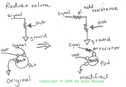
Reduce the volume of a circuit
Most circuits have a volume control at the end. Sometimes you want the overall level of the pedal to be lower and for the volume control to "sweep" in a lower range. To do this, insert series resistance (i.e. put a resistor inline) with the volume pot.
"Hi-Fi" or "Studio Quality"
mod.
Convert as many ceramic caps to film, change resistors to metal film.