 Here is the pinout
for the 2N5087 transistors. There are 2 of them in this circuit.
Here is the pinout
for the 2N5087 transistors. There are 2 of them in this circuit.Copyright © 2005 by Aron Nelson, All Rights Reserved.
Joe Davisson recently posted a cool looking circuit. It's a discrete op amp with diode compression. A circuit that could be used with my op amp circuits and has properties of the Vulcan? It looked too cool to pass up, so I decided to wire it up. Here are the steps for the perfboard layout. 1/30/05 Build is verified and it sounds GREAT! I used it as a replacement for an RC4558 with great succes! (This will replace one of the dual op amps in the chip).
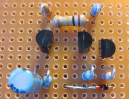
I'm using Pad-Per-Hole perfboard to wire up this circuit.This is a relatively simple build so this would make a good second project. For a first project, see the Beginner Project.
The first thing I always do is to sketch out the circuit in my book. I start with transistor pinouts and then sketch out the entire circuit.
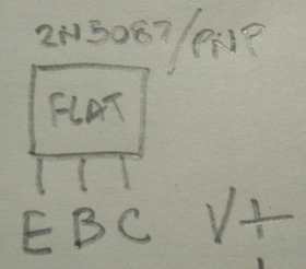
Here is the pinout
for the 2N5087 transistors. There are 2 of them in this circuit.
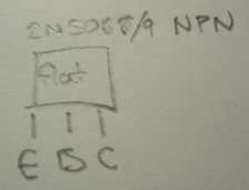 Here is the pintout
for the 2N5089 transistor in the circuit. In both sketches of the pinout, this
is with the flat side of the transistor facing up.
Here is the pintout
for the 2N5089 transistor in the circuit. In both sketches of the pinout, this
is with the flat side of the transistor facing up.
Here's the sketch of the circuit. It's kind of a psuedo circuit drawing. Sorry about the corrections on the page. The layout is for looking at the bottom of the perfboard looking through it - as if you could see through it.

On the right is the pinout of the op amp that I hope to sub with this circuit.
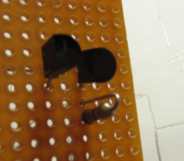
I start with the first 2N5087 transistor. I place it a few pads in the board so I have room to place an input wire.
![]()
I place the second 2N5087 on the board. I separate them by one pad for clearance.
![]()
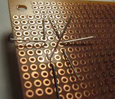
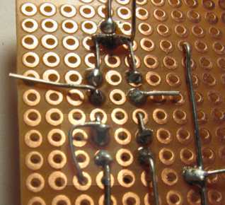
Here's how I aligned the leads of the transistors on the bottom. I'm basically laying it out like the schematic.
![]()
OK, now I place the 6.8K resistor. I like to stand my resistors up on end for space reasons. You don't have to do this, you can lay them down.

I cut the lead of the first 2N5087 to prepare for the 6.8K resistor. I try to cut the lead right around the middle of the hole.

Here's a picture of the bottom with the 6.8K lead touching the collector of the first 2N5087.
Here's how I place the resistor "on end" through the top of the board.
Here's the 10K resistor, again bent to fit on end.
Here's the bottom of the board with the 6.8K and 10K resistor leads sticking out.

Here's the top of the board with the 6.8K and 10K resistors on end.
Here's the bottom after I solder the 2N5087 transistors to the 6.8Kand 10K resistors.

Next I place connect the two 2N5087 emitter leads together and connect the 10K resistor to the emitters of the 2N5087 transistors.

Here is the circuit with the leads trimmed.

The top of the circuit so far.

OK, onto the 100K resistor that bridges the emitters of the two 2N5087 to the output stage of the 2N5089.

Here is the top view. I decided to lay this resistor down flat since I wanted it to take up room horizontally.

Next I place the diode on the board and solder it to the 100K resistor. Hmm, that solder looks too big in this picture.

If you look at the schematic, the diode needs to connect to the collector of the first 2N5087 and not to the collector of the 2nd 2N5087. That's why I place the diode this way on the board.
See how the diode is placed?

Next I solder the diode to the first collector.

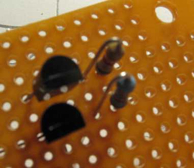
Up next is the output transistor. See how I place it in the board and bend the leads?
![]()
Here's the top view.
![]()
To mimic the schematic, I bend the "output" lead.
![]()
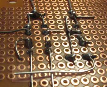
Here is the bottom of the board with the 2N5089 soldered in place.
![]()
At this point, I notice that forgot to solder the 10K resistor lead to the emitters of the two 2N5087. I do that now and snip the lead.

Next up is the 4.7K resistor on the collector of the 2N5089 transistor.Insert the usual way and solder.

Then the 1K resistor on the emitter of the 2N5089. I bend the leads to hold the resistor in place.

Here's the top of the board so far.

Next up is the 22uF electrolytic cap. The black band is the negative lead.

I place the 22uF cap through the board observing the polarity and bend the leads as usual.

I then cut the leads in preparation for soldering.

OK, the circuit is nearly finished, I connect the grounds together by bending one lead over.
I solder the grounds together and snip the leads.

OK, let's connect the top two leads that go to V+, this is the last step.

and solder...

Here is the discrete op amp w/compression top of board! Read to wire up!