I recently purchased a very good condition JP-8000. After changing the battery, I noticed that the volume was extremely low on the line outs. The headphone out was working perfectly and after asking around, I was told, why not tap the headphone outputs to the line outputs??? What a great idea!
!!!!!!!!WARNING!!!!! Do not attempt this if you are unfamiliar with basic soldering and working with electronics. UNPLUG your board before working with it. This WILL VOID your warranty.
Here are the steps:
Disassemble the JP-800. All the screws on the bottom come out except for the screws holding the rubber feet. Lift the particle board bottom off the unit.
Locate the output board - this is the one that is closest to the output jacks. There are 3 screws on the outside (2 are different, so remember where they go). There is one ground wire on the board that connects to the chassis. You will probably want to remove this as well to get access to the bottom of the board.
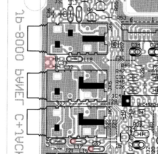
Locate L15, L17, C32,C33, C36 and C37. These are the components you will be working with. Once you have located everything, proceed with the mod.
Boost Mod:
Desolder and lift the ends of L15 and L17 closest to the output jacks.
Desolder and lift the ends of C32 and C33 closest to the output jacks.
I used a combination of solder sucker (plunger type and solder wick) to get the solder off the pad. Once the pad was “clean”, I then pushed the component lead from the bottom of the board back through the pad hole with a screwdriver. I then lifted the end of the component using a needle nose plier. Make sure that the component lead is no longer touching any part of the pad.
The ends of the components that you have to lift are in pink below.
Pads desoldered.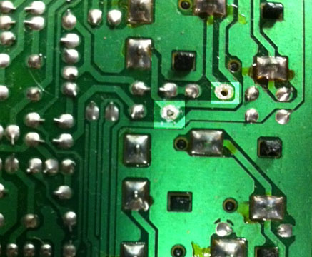
L15 and L17 lifted. C32 and C33 on far right.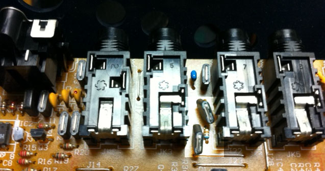
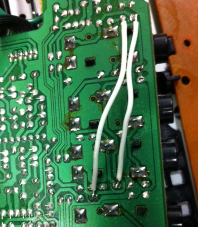
Connect the pad of C36 which is closest to the jack to the pad of L17 (the pad that you disconnected) with an insulated wire underneath the board.
Connect the pad of C37 which is closest to the jack to the pad of L15 (the pad that you disconnected) with an insulated wire underneath the board.
The wires connect as shown in red. Note that this is UNDER the board. Use 22-24 gauge insulated wire (hook up wire).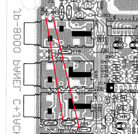
Put the board back together.
This mod totally fixes the low output of the JP-8000 and makes it an output monster! What this does is tap the output of the headphone jacks - which has plenty of output and connects it to the output jacks L and R. The bonus is that the left side will mix the two outputs into MONO like it should.
For reference, here is the schematic of the output.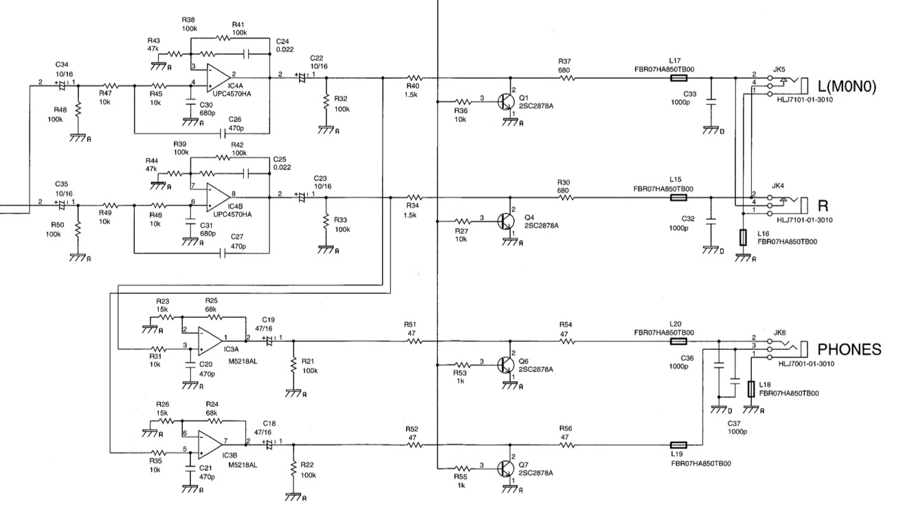
JP-8000 Roland Corporation.