DIY Breadboard
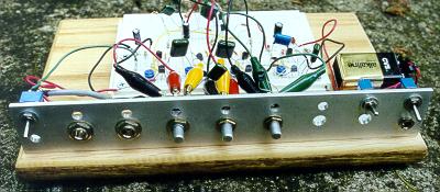
Here is a simple project that will greatly quicken and simplify testing circuits. The idea originated from RG Keen's website, GEO. Check out RG's instant effects breadboard. Note that similar drill patterns were used to mount the pots and switches.
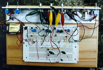
This project used a piece of oak plywood with 10 by 6 1/2 dimensions. The edges were rounded with a router and a couple of quick coats of wood finish were applied for protection. 1 1/2-inch aluminum angle was used to mount the pots, jacks, and switches, etc. The input and output jacks were permanently mounted with a DPDT toggle switch so the circuit can be quickly bypassed. There is also a permanent power switch, which accepts either a 9V battery or a DC voltage through the power jack. The actual bread board part consists of two individual breadboards that I picked up at Radio Shack. I'd recommend using even three of these, as prototyping real-estate quickly vanishes when testing larger circuits.
If you go through the trouble of making this, you might as well build two together, as one breadboard is simply not enough!
Note-- the wires connecting the pots to the board consist of an alligator clip attached to the wire, with a (resistor or capacitor) lead soldered to the other end. This lets me quickly connect an off-board part to the rest of the circuit.
Not exactly a breadboard, but here's a picture of a transistor gain tester. Follow these directions by Steve Daniels. With this jig, you can simply clip onto the DMM leads and supply power. There is no re-clipping. You just pop the transistor into the transistor socket, measure the current on the first DMM, flick the switch on the jig (hard to see but to the left of the socket) and measure the current on the first and second DMM. When done, you can exchange transistors and repeat. This speeds up the process, especially if you have a lot of transistors to test. Label the wires on the perfboard to avoid confusion.
![]()