Shaka Braddah Notes
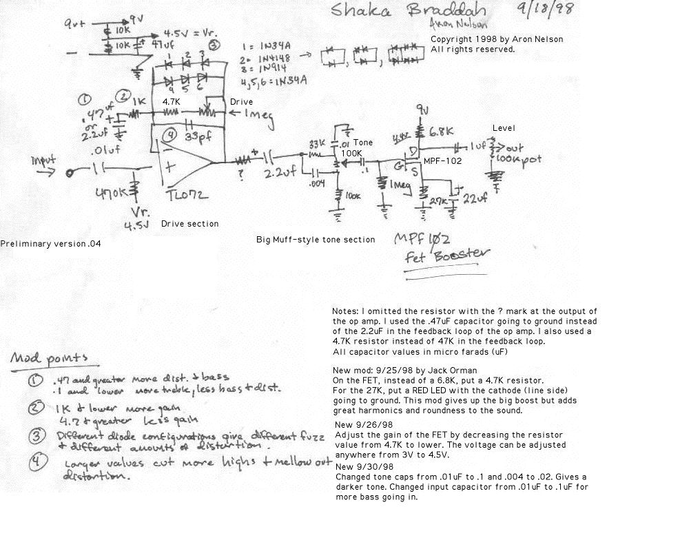
11-27-98 - New addition from Alfonso Hermida. Alfonso recommends putting a preamp stage before the input of the Shaka Braddah. It boosts the level going into the pedal and should give more sustain and let the IC work more efficiently. I also applied the following changes to the circuit:
I put in Alfonso's preamp in front of the Shaka Braddah.
Instead of the 6 diodes, I put a single 1N34A on one side and a 1N914 on the other. The circuit distorts more readily with this combination.
I used a genuine Radio Shack MPF102 for the output FET booster.
Instead of the 33pf cap next to the diodes, I used a 220pf cap to cut more highs.
For the biasing resistor from 9V to drain of the FET I used a 10K trim pot from Radio Shack so I can tune the circuit to my different FETs. I also used a transistor socket so I could experiment with different brands of MPF102s.
I used the .47uf cap at point 1 from feedback loop to ground.
I used a 500K pot instead of 1MEG.
The result is a smooth distortion through my amp. However it seems that I can still hear the clean signal as well through the distortion pedal. Pretty interesting. I will be experimenting more with this circuit soon.
I think I may put a resistor/capacitor filter to roll of a little more highs since the FET booster adds them into the signal.
9/25/98 - New Mod by Jack Orman. Here's a red heart for the Shaka Braddah! This mod will give the Shaka Braddah more harmonics and fullness with the expense of the big boost. Two components need to be changed on the FET booster at the end of the circuit. The mod is noted in the schematic. Basically the 6.8K resistor is changed to 4.7K and the 27K resistor is changed to a RED LED with the cathode going to ground. To see where this idea came from, look at Jack Orman's FET output circuit.
9/26/98 - More modification of the output stage. In order to get a good boost going again, you need to lower the value of the resistor going from 9V to the drain of the FET (MPF102). Adjust the value until you get 4.5 volts or so. I used a 1K resistor but I don't know what effect the type of LED has on the biasing of the circuit. To check the voltage, set your multimeter to DC and connect the black probe to ground and the red probe to the drain of the FET, try different resistor values until you get the gain you want.
9/28/98 - More on the biasing resistors. I have found that the MPF102 FETs I got from JameCo are way different in terms of biasing! To get the same 4.6V at the drain, I have to use a 680 ohm resistor. With a Radio Shack MPF102, I use a 2.2K resistor. Quite a big difference. Basically you need to measure the voltage with your multimeter and sub resistors until you get what you want at the drain.
I really like this circuit!