- Welcome to DIYstompboxes.com.

DIYstompboxes.com
News:
SMF for DIYStompboxes.com!
Recent posts
#1
Digital & DSP / Digital to analog - help
Last post by caspercody - Today at 09:27:03 PMHello
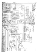
I am trying to make a ADA MP1 pedal of the tube/solid state circuits. I have them almost built, but I am having issues with the (I think) digital chip TC9176.
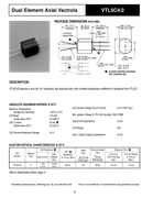
This TC9176 is used as a pot with inputs from push buttons. Then I think the output of the TC9176 is digital to some IC circuits that convert to analog to drive a VTL5C4/2 Vactrol that is adjusting the OD1 and OD2 volumes.
These circuits are around U5, U9, and U14 for the OD1 volume. For OD2 they are U3, U2, and U14. Also OD2 is used to adjust the compression circuit when in solid state mode (going into U6).
I was also wondering if I could create a circuit with a pot to vary the LED portion of the VTL5C4/2's? If this would work I could eliminate U2, U9, and U14.
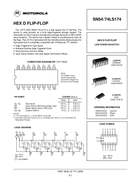
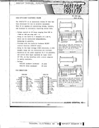
Looking at the TC9176 circuits I do not understand the STB, DATA, and CLOCK inputs. I see these points are connected to a 74LS174 (U27) chip, then to a 74LS138 (U39) chip, then to the main board Z80 (U29). The push button membrane come to the main board through other chips. I know this circuit is very old, and there is probably an easier way to get this done. I just do not know how, and I do not know enough looking through Google.
I have tried just using a pot in place of the TC9176, it worked but turning the pot had no consistency

.
Thanks
Rob
I am trying to make a ADA MP1 pedal of the tube/solid state circuits. I have them almost built, but I am having issues with the (I think) digital chip TC9176.
This TC9176 is used as a pot with inputs from push buttons. Then I think the output of the TC9176 is digital to some IC circuits that convert to analog to drive a VTL5C4/2 Vactrol that is adjusting the OD1 and OD2 volumes.
These circuits are around U5, U9, and U14 for the OD1 volume. For OD2 they are U3, U2, and U14. Also OD2 is used to adjust the compression circuit when in solid state mode (going into U6).
I was also wondering if I could create a circuit with a pot to vary the LED portion of the VTL5C4/2's? If this would work I could eliminate U2, U9, and U14.
Looking at the TC9176 circuits I do not understand the STB, DATA, and CLOCK inputs. I see these points are connected to a 74LS174 (U27) chip, then to a 74LS138 (U39) chip, then to the main board Z80 (U29). The push button membrane come to the main board through other chips. I know this circuit is very old, and there is probably an easier way to get this done. I just do not know how, and I do not know enough looking through Google.
I have tried just using a pot in place of the TC9176, it worked but turning the pot had no consistency
.
Thanks
Rob
#2
Building your own stompbox / Re: Christine!!!
Last post by Matthew Sanford - Today at 03:01:21 PMFunny, you'd got my brain thinking and now I come back feeling bad to bring it to the top but to throw more madness on the fire! I hadn't noticed the power cap on TTG's scheme but it's there, and 1k to Vcc. Here, Taylor took that 1k out and put the diode protection with the cap, plus he didn't like the buffers, said more responsive to guitar tone/volume knobs without them...but I wonder if the lack of the Vcc resistor also influenced that? I know, even buffered, 47R Vcc resistor, etc, it will go cleaner with the volume knob down.
What got me back (in the nick of time!) was the power starve, the Vcc resistor, the fact that resistance to either ground or Vcc seem to create more distortion, then thinking what if you took the two power starve inverters set them like the power starve as singles to both pin 1 and pin 8, maybe a dual 100k pot. I would think that current limiting in both ways would kind of make distortion out of it more symmetrical, but not really sure on it. For sensibility's sake I've put an order to the things waiting for me to work them, but I think when the breadboard comes back out I may just put her on it again. I love the boxed one I have, but would like her to work with whatever goes in, or not I guess if she gets really silly. Plus, I want to see what getting gain/distortion from the input buffer would do, would that keep the signal strong enough to not glitch so much or is that more on the messing with power rails part? So many questions...
Interesting mods you make, I assume those two are the old power starve ones for the square...might be interesting to just throw that square into the oscillator section. I can't help but love putting the (L)DR. LEDs on the pots, but I've been thinking what it might sound like with the LFO level lower, for more a wobble instead of extreme resistance changes - I'll try it. Then thinking on the tap tempo thing to replace a schmitt might be better to replace the triangle back to the schmitt, and I think with how I'm putting triangles in (like that other thing) it would make the rate pot on the triangle then turn in to the depth with it wobbling offset to the Vb on it...hmmm... another post, that.
#3
Building your own stompbox / Re: Inductor polarity question
Last post by eh la bas ma - Today at 02:57:55 PMQuote from: Rob Strand on Today at 01:29:17 AMTo cut to the chase: I suspect the designer has found orientating the inductors a certain way helps reduce noise induced by the inductors. You will find in practice this will be the case. All you have to do is put one inductor in arbitrarily then see which orientation of the other inductor gives the lowest noise. Maybe you can't tell the difference.
Thank you very much fort these clarifications !
I soldered the 2.2mH in a random orientation, and i will change it if i have some noticeable background noises. I wasn't sure if i could damage the part or the circuit with some wrong orientation, so now i can proceed with the build without doubts.
Thanks !
#4
Building your own stompbox / Re: Christine!!!
Last post by duck_arse - Today at 10:47:29 AMsee this again. +9V and ground are bypassed with that 10uF, so AC grounds. see how pin 8 has the power starve rubbish between ground and Vss. so all that resistance is unbypassed. and the chip, from Vcc to Vss is also unbypassed. any current that flows through the starve causes a voltage drop across the starve, and there is no cap there, anywhere, to catch and hold those wobbles. so all the invertors cop the wobbling, whether they want it or not.
same will apply if you have shifted Vc from Vcc by inserting a resistor, 47R or not, between supply and pin 1. you would then have an un-bypassed point, Vcc, which will wobble with current.
how much capacitance, and where you put it, will affect differently. trust me, I've heard it.
now here, look, I know you are also worried about those two unused invertors, I know I am.
make an oscillator, you probably need one. it will square wave, it probably won't drive a led directly, so use a pnp [connect sq_OUT to sq_IN] and there will be no silly confusions about supply and ground. the led can do anything you want, brightness via R4 value -- or you can use the transistor to shunt, say, another resistor, maybe in the starve line. no ldr!
be warned - I have this working on the breader in total isolation. I haven't tried varying the supply, or starving the supply, but I'm fairly sure the set frequency will jump about with all the supply funnies all your leds will be inducing. so, mayhem, probably. but no leftover IC.
#5
Building your own stompbox / Re: The Psychotenuse Tremolo.....
Last post by duck_arse - Today at 10:19:52 AMthere. now I've drawn a line.
two things; junior. how are his eyes for colour sight, good? get him to squint at the resistors. photos. we don't know what you've done, no matter how many layouts you post, if you don't show us the photos, so we can then look. if you post it, they will look, like costner sez.
is there any chance you have the pot wiper on its own, and the two ends of the pot joined? I have licence to ask because of the symptoms, and the lack of photos. [ comment removed here ]
also - small a, small d. thank you [from the possums].
#6
Pictures / Re: Pictures!
Last post by Phend - Today at 09:48:11 AMI attach two pieces of acrylic to the top of a 1590BB Hammond box with four screws. The top is clear to protect the floursent piece from scratches. I have etched photographs on clear acrylic. Using the correct techniques they are outstanding. Another project. The neat thing about screwed on "art" is they can be changed in a minute.
#7
Pictures / Re: Pictures!
Last post by amptramp - Today at 08:28:28 AMQuote from: Baran Ismen on Today at 03:22:00 AMQuote from: Phend on April 15, 2024, 11:35:09 AMAdding black behind florescent is a good idea.
Actually using a plexiglass is alone a good idea! You can use a transparent one, paint it with any color, laser engrave the design on it, cut the holes and put some leds inside, too.

Make sure you have some means of shielding the circuitry behind the plexiglass. You can use metal foil or screening to ensure that signals do not get in or out.
#8
Building your own stompbox / Re: Tube Cricket Vero Layout
Last post by GibsonGM - Today at 05:51:52 AMSorry, don't know - but this one would make a great point-to-point build on terminal strips, just working from the schematic. The last stage with the 386 would be all that one needs a small piece of perfboard for. Just offering encouragement 
#9
Building your own stompbox / Re: Inductor polarity question
Last post by Elektrojänis - Today at 04:45:01 AMI wonder if in addition to the magnetic field direction and magnetic bias, the circuit impedances on the ends of the coil could have an impact on the induced noise?
I mean if you connect the end of coil thats connected to the outer layer of the coil to lower impedance point, would it have similar shielding effect as with capacitors, when you connect the end that connects to the outer foil layer to the lower impedance point? With inductors this would only work on those that have several layers of copper wire.
I mean if you connect the end of coil thats connected to the outer layer of the coil to lower impedance point, would it have similar shielding effect as with capacitors, when you connect the end that connects to the outer foil layer to the lower impedance point? With inductors this would only work on those that have several layers of copper wire.
#10
Building your own stompbox / Re: Tube Cricket Vero Layout
Last post by Valleyslad - Today at 03:54:26 AMSorry to bump such an old thread, but is there now a verified layout for this?