- Welcome to DIYstompboxes.com.

DIYstompboxes.com
News:
SMF for DIYStompboxes.com!
Recent posts
#11
Pictures / Re: Pictures!
Last post by Baran Ismen - Today at 03:22:00 AMQuote from: Phend on April 15, 2024, 11:35:09 AMAdding black behind florescent is a good idea.

Actually using a plexiglass is alone a good idea! You can use a transparent one, paint it with any color, laser engrave the design on it, cut the holes and put some leds inside, too.
#12
Building your own stompbox / Re: "Noise Ensemble" - simple ...
Last post by sinthmart - Today at 01:51:20 AMThank you for bringing the topic back. Only now I saw where the circuits with 2399 that I saw before came from. All original photos of the diagrams have disappeared over time. And it would be interesting to see the original scheme with which it all began. that's her?

#13
Building your own stompbox / Re: Inductor polarity question
Last post by Rob Strand - Today at 01:29:17 AMIn normal circumstances you don't care about the "polarity" of such inductors and in fact it is rarely given. While the Bourns inductors show a dot for the start of the winding that alone doesn't determine the "polarity", it also depends on the winding direction.
You can get magnetically biased inductors, which look similar, and these do have a polarity and have magnets attached to the core. These were common in CRT monitors. The Bourns units are not this type.
Polarity would be defined, for example, as the magnetic field pointing in some direction when position current is applied to a certain pin. There is no standard for it. You can't be certain all brands of inductor are wound with the same direction so determining the start of the winding isn't sufficient.
To cut to the chase: I suspect the designer has found orientating the inductors a certain way helps reduce noise induced by the inductors. You will find in practice this will be the case. All you have to do is put one inductor in arbitrarily then see which orientation of the other inductor gives the lowest noise. Maybe you can't tell the difference.
If the external field is a problem the solution is to use magnetically shielded inductors.
Based on the assumption that the Bourns units are wound in the same direction it might be possible to set-up an experiment with an oscilloscope, or with an LCR meter, to work out the relative polarities of connections. In some cases you might be able to eyeball the winding start and winding direction. You might even be able to use a compass (apply a current an choose leads which cause the same direction of field out the top of the inductor.).
#14
Building your own stompbox / Inductor polarity question
Last post by eh la bas ma - Yesterday at 10:05:52 PMHello,
I am building Schalltechnik-04 Omnilooper :
https://schalltechnik04.de/en/instructions/omnilooper/6
p.6 they say the 2.2mH has to be aligned correctly, dot to dot (there is a dot printed on the pcb).
Unfortunately the inductor musikding provided has no dot, and both legs have equal length. All i can notice on the part is the number 36, a "c" small letter, and an "R" capital letter reversed, like the russian Я. These symbols are located on the side of the part, at equal distance of both legs, so it doesn't look like some orientation marker.
Looking at the part from every angle, i can't see any marker anywhere...
The two other inductors were in a plastic bag labelled "Bourns 222 K2" and have dots. This inductor, twice as big as the two other 1mH, same color, is on its own, no label.
I wonder how can i figure its orientation ?
I tried to check the datasheet of an inductor that could look like this one, from Bourns, but i couldn't find any clue.
https://media.distrelec.com/Web/Downloads/_t/ds/rlb-series_eng_tds.pdf
Looking online for a way to test its polarity, it looks like a multimeter won't be enough, i would need an osciloscope or some special meter that i don't have.
Any help would be welcome !
#15
Building your own stompbox / Re: The Psychotenuse Tremolo.....
Last post by moid - Yesterday at 06:40:24 PMFirst Raccoon: Whaddaya mean we put the wrong value resistor in R1? Duck_Arse is gonna go crazy at us; we only just got away with that last screw up - he's bound to see through our disguise this time!
Second Raccoon: Yeah I've no idea how we did it - putting a 15K where we should've put a 100K resistor! It makes no sense; we're always so careful with resistors...
First Raccoon: yeah because everyone knows racoons are colourblind, so we always use the DMM to check each resistor don't we?
Second Raccoon: I don't know how that went wrong; we have a system and all raccoons use the system, don't we? Raccoon three uses the DMM on the resistors and passes them to me, I solder them and you check the schematic! Foolproof! Only a fool could screw that up...
Raccoon number One and Two turn to face Raccoon Three
Raccoon Three: Errrrmmmm...
Raccoon One: You didn't use the DMM did you dum-dum?
Raccoon Three: Errr yes I did, mostly... sometimes... sorry fellas... I kept thinking about how girls love reverse sawtooth tremolo...
Raccoon Two: Quite understandable - those are very distracting thoughts, why I sometimes have them myself...
Raccoon One: I'm surrounded by knuckle heads! If we don't follow the system, then we don't get the reverse sawtooth tremolo, and if we don't get the reverse sawtooth tremolo then girls are right off the menu!
Raccoon Two and Three: Sorry boss
Raccoon One: OK well fix the damn circuit and let's see what happens!
sounds of welding, metal plates being hit repeatedly, geiger counters clicking and a Van Der Graaf generator powering up, someone loops the first line of The Special's "Man at C&A"
Raccoon Three: OOoohhh the lights are all flickery now!
Raccoon One: Great work team, now what do we tell Duck_Arse?
Raccoon Two: Maybe we should say we had a cold solder joint? That could happen to anyone, even pros get those!
Racccon One: Brilliant! Why I think I hear him coming, OK guys, solder casual, play it cool...
Moid: Oh hi there Duck, hey you'll never guess what was wrong with that circuit? I just needed to reflow the solder, must've been a cold solder joint somewhere - it works now* Huh, Who would've thought a little thing like that caused all those problems? Couldda happened to anyone...
* ok at this point I have to snatch defeat from the jaws of victory. The circuit kind of works. It does not like a 15K resistor, nor does it like the 100K resistor which works perfectly on the breadboard version of the circuit; it in fact likes the 33K resistor that you suggested in the first place. So that is in place (socketed). The LEDs now flicker rapidly. The sound however has really bad ticking in it and the tremolo sound is a bit gentle (I've wrapped the LED LDR combos in black insulation tape so I know there aren't any light leaks). However most disastrously, the circuit only works when powered by a 9V battery! As soon as I plug it into a wall wart 9V DC plug the Blue LEDS stay on and do not flicker, and the Red LEDs turn off. Also if I connect the circuit to any other pedal that uses mains power (9V) the circuit does the same thing - blue LED on, Red off, no flickering. I realised that in the video that inspired this crazy circuit, the guy who made it only used a battery to power his pedal... and when I breadboard things, that breadboard runs off a battery as well (I never liked the idea of mains electricity going to something that I am sticking my fingers into)... so presumably there is something in the circuit design that breaks if it doesn't have a battery attached? That is pretty weird! I think this one might be being chalked up to nice idea, but isn't very practical / reliable... and it's weird that two different C106D transistors require totally different values of resistor to fire up... quelle strange!
I noticed when I play through the circuit that loud chords will distort (not a bad thing as such, but very surprising considering the audio part of the circuit is supposed to not be attached at to the tremolo part), and also as a note decays the trem can slow down a bit and then stop, and I have to mute the strings to force it back on! Also I wired the pot wrong so that you have to turn clockwise to slow the rate down, so I switched the wiring and now (even with a 100K resistor on the pot as well) it seems to lock up at both ends of the pot sweep, but play fine in the middle. Now I wondered if somehow the audio is getting into the current that makes the tremolo work and I think I might need to put a cut on row J between the 1n4148 and the blue jumper on the right side of the board - does that sound like a good idea? New layout below

I do hope you aren't pulling your hair out or cursing my existence at this point (thanks again for your patience!)
That would be my plea anyway! If this circuit doesn't work then I suspect my next brilliant circuit idea (which steals from this one) is possibly dead in the water...
Second Raccoon: Yeah I've no idea how we did it - putting a 15K where we should've put a 100K resistor! It makes no sense; we're always so careful with resistors...
First Raccoon: yeah because everyone knows racoons are colourblind, so we always use the DMM to check each resistor don't we?
Second Raccoon: I don't know how that went wrong; we have a system and all raccoons use the system, don't we? Raccoon three uses the DMM on the resistors and passes them to me, I solder them and you check the schematic! Foolproof! Only a fool could screw that up...
Raccoon number One and Two turn to face Raccoon Three
Raccoon Three: Errrrmmmm...
Raccoon One: You didn't use the DMM did you dum-dum?
Raccoon Three: Errr yes I did, mostly... sometimes... sorry fellas... I kept thinking about how girls love reverse sawtooth tremolo...
Raccoon Two: Quite understandable - those are very distracting thoughts, why I sometimes have them myself...
Raccoon One: I'm surrounded by knuckle heads! If we don't follow the system, then we don't get the reverse sawtooth tremolo, and if we don't get the reverse sawtooth tremolo then girls are right off the menu!
Raccoon Two and Three: Sorry boss
Raccoon One: OK well fix the damn circuit and let's see what happens!
sounds of welding, metal plates being hit repeatedly, geiger counters clicking and a Van Der Graaf generator powering up, someone loops the first line of The Special's "Man at C&A"
Raccoon Three: OOoohhh the lights are all flickery now!
Raccoon One: Great work team, now what do we tell Duck_Arse?
Raccoon Two: Maybe we should say we had a cold solder joint? That could happen to anyone, even pros get those!
Racccon One: Brilliant! Why I think I hear him coming, OK guys, solder casual, play it cool...
Moid: Oh hi there Duck, hey you'll never guess what was wrong with that circuit? I just needed to reflow the solder, must've been a cold solder joint somewhere - it works now* Huh, Who would've thought a little thing like that caused all those problems? Couldda happened to anyone...
* ok at this point I have to snatch defeat from the jaws of victory. The circuit kind of works. It does not like a 15K resistor, nor does it like the 100K resistor which works perfectly on the breadboard version of the circuit; it in fact likes the 33K resistor that you suggested in the first place. So that is in place (socketed). The LEDs now flicker rapidly. The sound however has really bad ticking in it and the tremolo sound is a bit gentle (I've wrapped the LED LDR combos in black insulation tape so I know there aren't any light leaks). However most disastrously, the circuit only works when powered by a 9V battery! As soon as I plug it into a wall wart 9V DC plug the Blue LEDS stay on and do not flicker, and the Red LEDs turn off. Also if I connect the circuit to any other pedal that uses mains power (9V) the circuit does the same thing - blue LED on, Red off, no flickering. I realised that in the video that inspired this crazy circuit, the guy who made it only used a battery to power his pedal... and when I breadboard things, that breadboard runs off a battery as well (I never liked the idea of mains electricity going to something that I am sticking my fingers into)... so presumably there is something in the circuit design that breaks if it doesn't have a battery attached? That is pretty weird! I think this one might be being chalked up to nice idea, but isn't very practical / reliable... and it's weird that two different C106D transistors require totally different values of resistor to fire up... quelle strange!
I noticed when I play through the circuit that loud chords will distort (not a bad thing as such, but very surprising considering the audio part of the circuit is supposed to not be attached at to the tremolo part), and also as a note decays the trem can slow down a bit and then stop, and I have to mute the strings to force it back on! Also I wired the pot wrong so that you have to turn clockwise to slow the rate down, so I switched the wiring and now (even with a 100K resistor on the pot as well) it seems to lock up at both ends of the pot sweep, but play fine in the middle. Now I wondered if somehow the audio is getting into the current that makes the tremolo work and I think I might need to put a cut on row J between the 1n4148 and the blue jumper on the right side of the board - does that sound like a good idea? New layout below
I do hope you aren't pulling your hair out or cursing my existence at this point (thanks again for your patience!)
That would be my plea anyway! If this circuit doesn't work then I suspect my next brilliant circuit idea (which steals from this one) is possibly dead in the water...
#16
Building your own stompbox / Re: Dead Astronaut FX : F-24 M...
Last post by FiveseveN - Yesterday at 05:17:48 PMQuote from: eh la bas ma on Yesterday at 12:34:02 AMI just want a multi-fx stompbox with lots and lots of effects, in order to ease my burden when i am traveling.If this is the main goal and you don't want to set up for programming, why not buy one of the tiny commercial DSPs like Nux Mighty Plug?
#17
Building your own stompbox / Re: Dead Astronaut FX : F-24 M...
Last post by eh la bas ma - Yesterday at 05:09:17 PMQuote from: DrAlx on Yesterday at 08:50:00 AMQuote from: DIY Bass on Yesterday at 05:07:36 AMThere are a lot of patches collected together here https://mstratman.github.io/fv1-programs/
They are just collected from around the web, so they may not all work, but there are a lot here to try out
It seems those patches are in assembly language (ASM files). They need to be compiled using the spin assembler to produce hex code. Then you need another program for either PickIt or Arduino to burn the hex code to the EEPROM.
Not sure what my advice to a novice would be. You need instructions on:
1) How to compile ASM files to hex code using either the Spin assembler (which is for MS Windows only), or the alternative spin assembler (asfv1) which works on both Linux and MS Windows but its a command line program and you need install Python.
2) How to wire a Pickit or Arduino to the EEPROM.
3) What software to get on your PC to program the Pickit or Arduino so it can burn the hex code.
Maybe this is a question best asked on the Digital & DSP section of the forum.
Thanks for your replies !
I think you scared me a little bit. That doesn't look like something very enjoyable...
I guess i'll try to negociate with musikding to get some preloaded EEPROM, hoping to avoid expensive shipment fee from Pedal PCB...
Maybe i'll change my mind, but i really don't want to spend so much time and effort for digital effects. They don't even interest me that much : in most cases i prefer analog effects by far.
I'll talk to some friends with a little experience in digital fx, listen to what they have to say, and maybe i'll try something.
But now, i would rather pay some expensive shipment fee from the U.S. for 2 little PPCB EEPROM, than struggling for weeks with all this programming stuff.
I really thought The F-24 kit would include some home-made DeadAstronaut's patches, i should have looked closer. As a matter of facts, it's never mentioned anywhere so i should have known.
Probably because i'm used to PPCB FV-1 projects, which always include loaded EEPROM.
#18
Pictures / Re: Pictures!
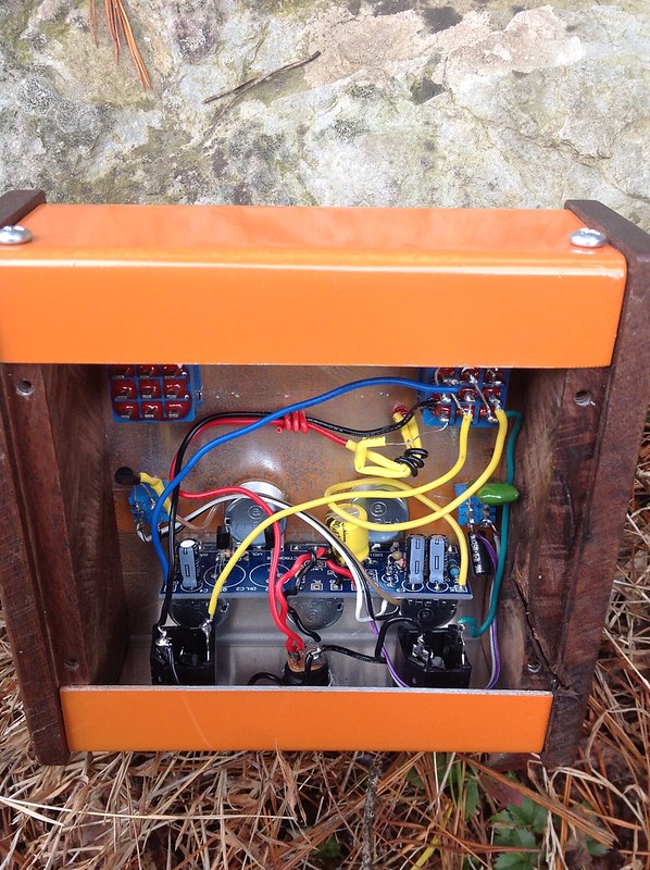
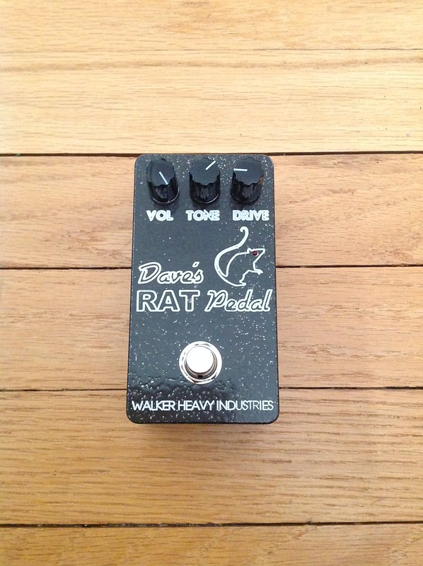
Last post by Mac Walker - Yesterday at 03:38:24 PMFuzz Factory and a RAT pedal for my friend Dave.
CNC engraved on a machine normally used for guitar making, no level compensation.


CNC engraved on a machine normally used for guitar making, no level compensation.
#19
Building your own stompbox / Re: UBE Screamer revisited
Last post by soggybag - Yesterday at 03:31:12 PMThe sound is similar. The difference isn't great but noticeable. I suspect there is enough phase shift from the distortion and filter sections that the out of phase from the buffer isn't as strong as it could be.
The trimmer between the input buffer and the ouput buffer has a greater impact on amount of distortion and over drive you can get.
The trimmer between the input buffer and the ouput buffer has a greater impact on amount of distortion and over drive you can get.
#20
Building your own stompbox / Re: Mutron V (madbean Kraken) ...
Last post by Kevin Mitchell - Yesterday at 12:53:12 PMQuote from: half_smith on April 16, 2024, 06:07:47 PMI did my best to build a "Neutron" with NOS Optocoupler but just can't get it to sound right, either misses the bias sweet spot or starts to sound overloaded, almost like feedback. I dunno...Did you fiddle with the drive pot at all?
You have to keep in mind that the Mutron III circuit was designed for a variety of instruments, so the effective range will be different depending on what you're plugging into it.
-No matter what you plug in, distortion & feedback is to be expected when the drive pot is cranked.