- Welcome to DIYstompboxes.com.

DIYstompboxes.com
News:
SMF for DIYStompboxes.com!
Recent posts
#21
Pictures / Re: Pictures!
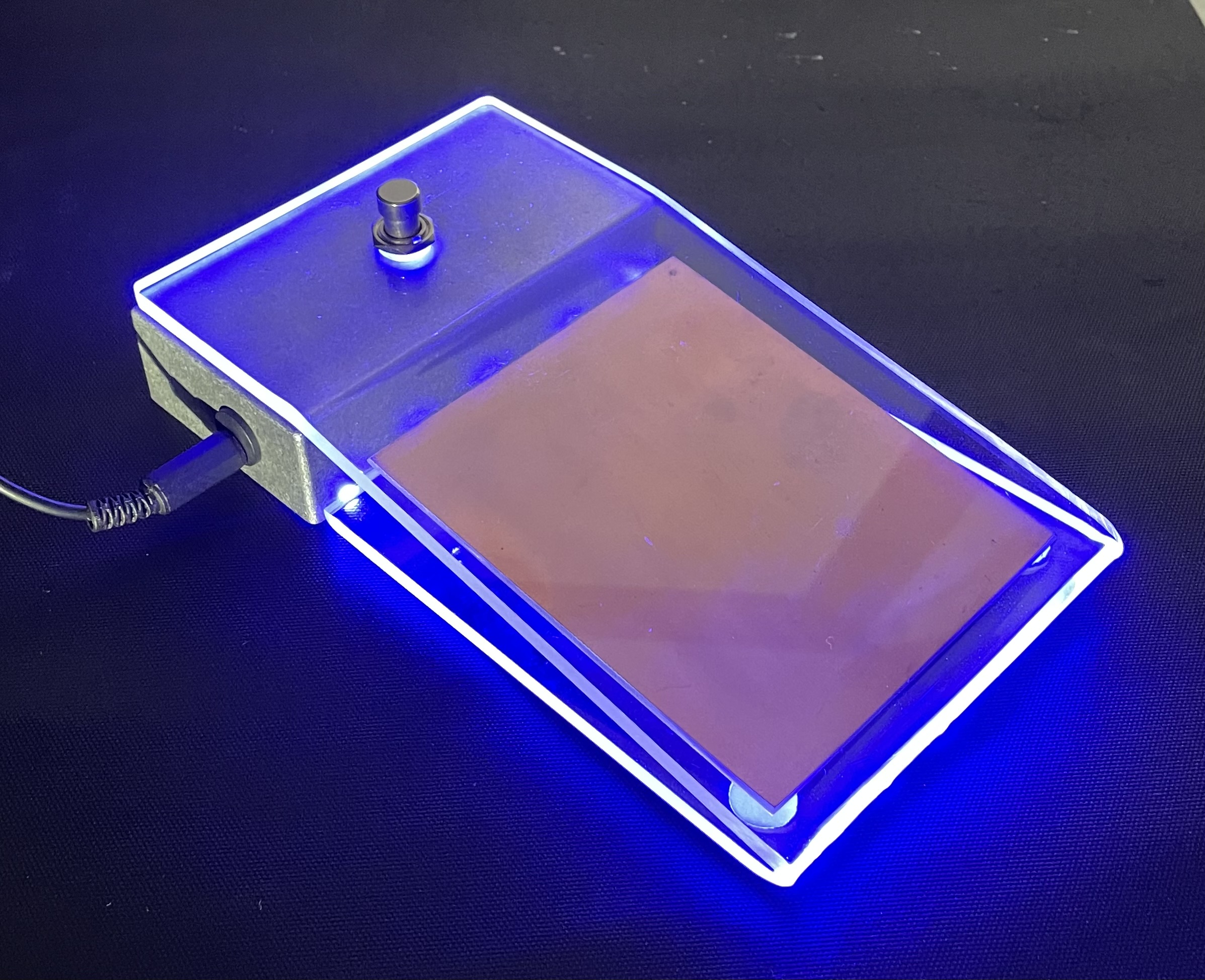
Last post by stallik - Yesterday at 12:39:49 PMLooks nice
I've seen signs where a single sheet of acrylic is mounted into a slot lined with led's. The slot hides the them but they illuminate the edges of the sheet and any engraving on it. Looks awesome but, its harder to hide the led's on a pedal.
Here's a proximity wah shell that i never got round to completing
#22
Building your own stompbox / Re: Christine!!!
Last post by duck_arse - Yesterday at 10:23:43 AMcan now report. that oscillator I showed, very nice osc it is, works a treat, values scale nicely - only, it's not for this pedal. when it runs, that's all you get. so it's just as bad as the original oscillations knob, when unfettered.
short answer - park those two unused invertors on Vss. long answer - I'm tempted to convert to a 4011, only four gates. but then they can be gated, externally. but then, they need more circuits to do the gating. but, the "more circuits" could have a proper supply section to theirselves, bypassed and all.
grrr.
#23
Building your own stompbox / Re: The Psychotenuse Tremolo.....
Last post by duck_arse - Yesterday at 10:17:25 AMwell, I have looked and compared, and I can't see it. the problem, I mean. obviously I can't say what about that switch in your circuit diagram, because it isn't there, so I can't say if it's right or not. but - all fingers are pointing to that particular black box, the footswitch board, that which we have no wiring diagram or schem or layout for.
only way I can figure to debug is to remove that board entirely. wire a switch as you think it ( can be a double pole toggle if you like ) to the oscillating section, and see if it functions right. then wire the audio part -- can even be on a seperate switch -- see if that holds up as you expect. and if it all comes together then, we/you have your/our answer/answer.
only way I can figure to debug is to remove that board entirely. wire a switch as you think it ( can be a double pole toggle if you like ) to the oscillating section, and see if it functions right. then wire the audio part -- can even be on a seperate switch -- see if that holds up as you expect. and if it all comes together then, we/you have your/our answer/answer.
#24
Building your own stompbox / Re: CV influencer! (broken NPN...
Last post by Matthew Sanford - Yesterday at 09:55:16 AMI figured, but for this one I want it in the box already, so the higher bias also works though may not hit the lows, and I don't have the time.
I have another to fix (add Rb, replace npns) which had worked fine, so I'm guessing it is proper and should act so
I have another to fix (add Rb, replace npns) which had worked fine, so I'm guessing it is proper and should act so
#25
Building your own stompbox / Re: FORUM downtime - April 15t...
Last post by Phend - Yesterday at 09:09:54 AM
#26
Pictures / Re: Pictures!
Last post by Phend - Yesterday at 06:52:49 AMQuote from: stallik on Yesterday at 04:56:49 AMHave you tried side illuminating those acrylic tops?Only with one led and natural light. So not from the side.
The florescent plastic would light up well with side lighting.
Have to think on how to do that.
Built an Axis Face with lite homemade knobs once.
But lighted pots for that are limited in values.

#27
Building your own stompbox / Re: FORUM downtime - April 15t...
Last post by amptramp - Yesterday at 06:50:42 AMLooks like it's back up to speed here as well.
#28
Pictures / Re: Pictures!
Last post by stallik - Yesterday at 04:56:49 AMHave you tried side illuminating those acrylic tops?
#29
Building your own stompbox / Re: CV influencer! (broken NPN...
Last post by antonis - Yesterday at 04:15:32 AMQuote from: Matthew Sanford on April 21, 2024, 03:08:45 PMOne bothersome thing, the Cf on the LPF (1st section) accounts for the npn voltage drop, the inverter Rf did not.
That shouldn't happen..
As long as BJT's B-E junction is set inside NFB loop, op-amps outputs should account for those VBEs..
(even for voltage drop inequalities..)
#30
Building your own stompbox / Re: FORUM downtime - April 15t...
Last post by bluebunny - Yesterday at 03:02:42 AMBack up to speed again this morning. 