- Welcome to DIYstompboxes.com.

DIYstompboxes.com
News:
SMF for DIYStompboxes.com!
Recent posts
#91
Building your own stompbox / Re: Resonant Filters
Last post by ElectricDruid - April 22, 2024, 04:33:20 PMIt looks a lot like you've been reading the SSI application note about designing analog filters with the SSI2164:
https://www.soundsemiconductor.com/downloads/AN701.pdf
...and quite right too! It's a fantastic document! It's pretty much a summary of about 30 years of synth filter history in about as many pages.
I notice you've halved the value of your R56 feedback resistor though. What's the purpose of that?
In general, the polarity of the resonant signal *always* matters! If it's not right, it won't resonate!
Whether 90 degrees is better than 270 I can't tell you. I agree with you that it doesn't *seem* like it matters, but a practical experiment would be the way to know for sure. Theory's great n'everyfing, but you can't beat a real-world bench test...
https://www.soundsemiconductor.com/downloads/AN701.pdf
...and quite right too! It's a fantastic document! It's pretty much a summary of about 30 years of synth filter history in about as many pages.
Quote from: Gobotak on April 08, 2024, 11:36:40 AMI would be fine with each filter being a first order filter if that saves on the number of required components.No, I think you've taken the right path going with 2-pole filters in both cases. You won't get effective feedback with a single pole filter.
QuoteThis is what I have drawn up for the low pass filter:The filter looks good to me. It's basically two stages of the classic four-stage synth filter, with the pole-mixing bandpass feedback from Fig.33 in the app note.
I'm going for bandpass resonance to avoid passband attenuation when using increased resonance. I'm wondering if the polarity of my resonant signal matters.

I notice you've halved the value of your R56 feedback resistor though. What's the purpose of that?
In general, the polarity of the resonant signal *always* matters! If it's not right, it won't resonate!
QuoteIf I am understanding correctly, each filter stage results in a 45 degree phase shift at the corner frequency so I would get a phase shift of 90 degrees from the filters.Correct.
QuoteI am using a VCA for the resonance so I get another 180 totaling 270.No. The *VCA* itself is inverting, but it's followed by an I-to-V op-amp stage (U4.2 in your lowpass schematic) which is also inverting, so there's no net inversion through the typical whole 2164 VCA schematic. <later note>I'm wrong! see further down the thread!
Whether 90 degrees is better than 270 I can't tell you. I agree with you that it doesn't *seem* like it matters, but a practical experiment would be the way to know for sure. Theory's great n'everyfing, but you can't beat a real-world bench test...
QuoteThis is the high pass filter:For the classic 4-pole case, the highpass version of the filter has the same problem as the lowpass version - the fed-back passband signal cancels the signal coming through the filter. So yes, I'd guess the bandpass feedback improves the situation for the highpass circuit just the same too.
Again I am going for bandpass resonance but I am not sure if it is needed.

QuoteAs is I would need 2 ssi2164s using 6 of the 8 VCAs leaving me two extra VCAs for other purposes.Yep! 3 VCAs needed for each two-pole filter with VC-resonance, and two left over for actual VCA duties, maybe?!
#92
Building your own stompbox / Re: Resonant Filters
Last post by PRR - April 22, 2024, 03:12:41 PMDon Lancaster Active Filter Cookbook is a good basic practical (and best selling) filter theory reference.
https://www.tinaja.com/ebooks/afcb.pdf
https://www.tinaja.com/ebooks/afcb.pdf
#93
Building your own stompbox / Re: Resonant Filters
Last post by Matthew Sanford - April 22, 2024, 03:10:01 PMI don't know enough, but you made me think to comments on Tom's FilterFX project page. He had stated " e.g. bigger resistance = less signal = less damping = more resonance.". For that pedal, it is a dual lpf for lp, bp, and hp options.
at here, hope it helps lead you along with ideas
at here, hope it helps lead you along with ideas
#94
Building your own stompbox / Re: Resonant Filters
Last post by Gobotak - April 22, 2024, 02:50:28 PMSince I'm new to filter design would you be willing to elaborate on that a bit more? In the low pass example my thought was that having second order band-pass feedback would give me resonance but it just would not self-oscillate. As for the high pass filter would feeding the output back into the input not achieve any resonance? Would there be resonance if there was second order band-pass feedback like in the example?
#95
Pictures / Re: Pictures!
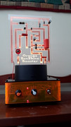
Last post by Phend - April 22, 2024, 02:10:00 PMPedal Board, bunch of classics, Peterson Strobe Tuner, Lcheapo silly scope.
Ge makes some noise, always did.
An interesting wall hanging when not is use.


Done , good luck all
Ge makes some noise, always did.
An interesting wall hanging when not is use.
Done , good luck all
#97
Pictures / Re: Pictures!
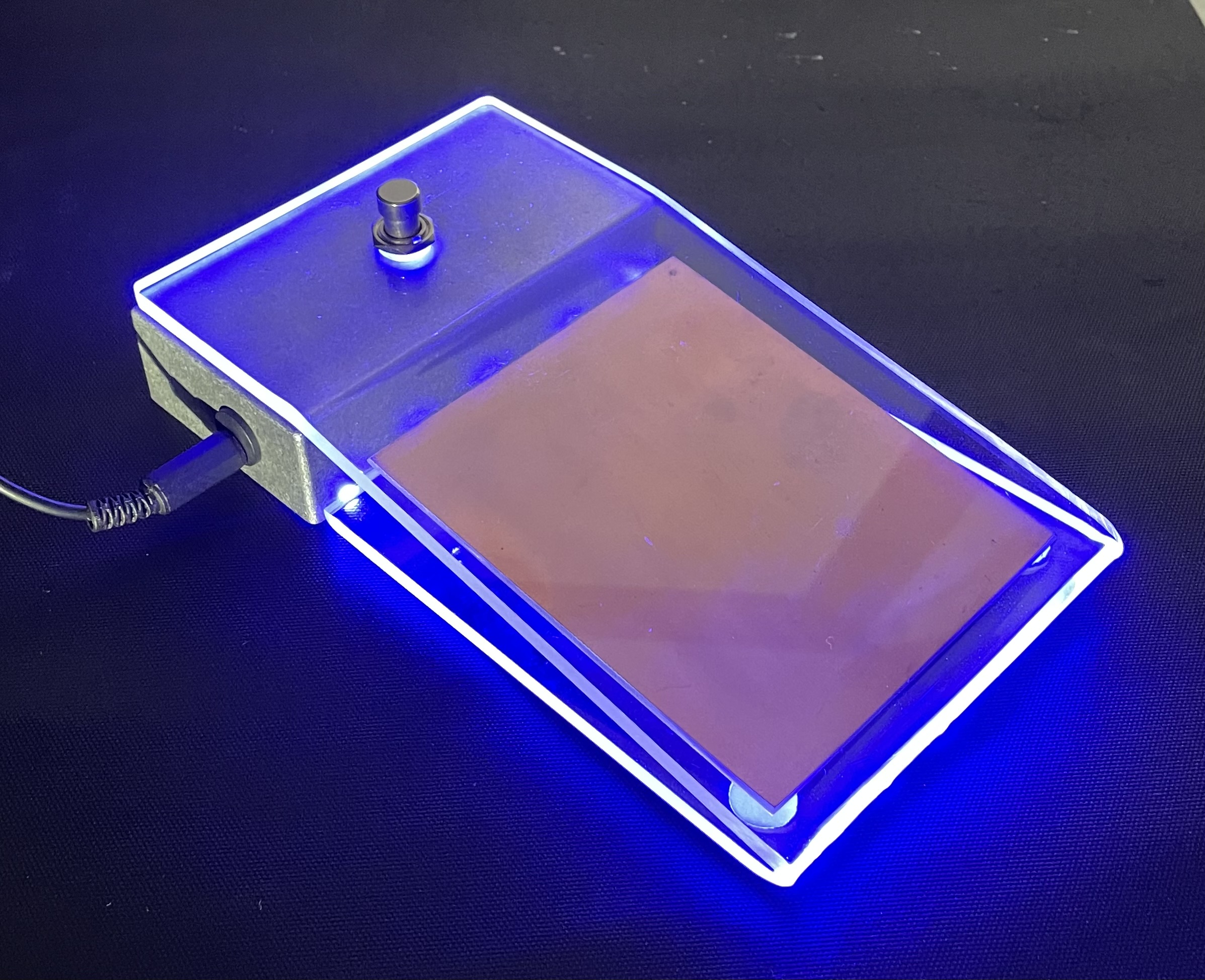
Last post by Phend - April 22, 2024, 02:01:08 PM"I've seen signs where a single sheet of acrylic is mounted into a slot lined with led's."
Yes I have seen those....


Yes I have seen those....


#99
Building your own stompbox / Re: Christine!!!
Last post by Matthew Sanford - April 22, 2024, 12:45:50 PMIt bothers me that she doesn't cooperate with only (well, seemingly) certain guitars. I'm thinking back, and she would cut or not before but has been well behaved for me - also, I got her to go the Taylor way (no buffers), no Vb on the input/output buffers, and with the Vb - but not always consistently.
Try the less gates way, it seems really the distortion comes from the resistance to ground from chip ground (and to Vcc as well), but really do those two need to get tied in to that? well... not really... I wonder with them straight to VSS while chip ground pin goes through resistance, what would that do? I guess you already worked those way...
Try the less gates way, it seems really the distortion comes from the resistance to ground from chip ground (and to Vcc as well), but really do those two need to get tied in to that? well... not really... I wonder with them straight to VSS while chip ground pin goes through resistance, what would that do? I guess you already worked those way...
#100
Pictures / Re: Pictures!
Last post by stallik - April 22, 2024, 12:39:49 PMLooks nice
I've seen signs where a single sheet of acrylic is mounted into a slot lined with led's. The slot hides the them but they illuminate the edges of the sheet and any engraving on it. Looks awesome but, its harder to hide the led's on a pedal.
Here's a proximity wah shell that i never got round to completing