|
The Beginner Boost - Breadboard-To-Box, A
Structured Approach
|
|
| © 2015 By Small Bear Electronics LLC |
|
|
|
If you are new to the Stompbox Forum, Welcome! I have been a visitor and
occasional contributor here over the last 15+ years. As a matter of full
disclosure, I should add that I have been running since then one of the
world's largest suppliers of components specifically for building stompboxes.
As the audience of the Stompbox Forum has grown, so has Small Bear
Electronics. I have posted this article with the cooperation of Aron Nelson,
the originator of the Forum, as a tutorial for those who are complete
newbies to the art and craft of building stompboxes. I'll walk you through
setting up Gus Smalley's Beginner Boost V. 2 on solderless breadboard and
then show you how to turn the components into a gig-worthy pedal. You can
choose a generic build using components available from many sources, or a
"deluxe" build in my Bare Box #1. Note: If you buy any of the kits for the
Beginner Boost, part of the price goes to help support the Forum. |
|
|
|
What do I mean by a structured approach? From the beginning, I'll have you
work in a very carefully organized way. When setting up this relatively
simple circuit on the breadboard, for example, I'll show you how to lay it
out logically. You'll get a clear idea of how physical components relate to
a schematic drawing and start to build prototyping habits that will serve
you well later. When we commit to solder, I'll share ideas and techniques
that make for a reliable, professional-looking build. |
|
| Here's the basic circuit that we will set up: |
|
|
|
|
|
In order to keep it simple, this schem includes input and output
jacks, but not stomp switch or power switching; we'll add those when we do a
soldered build. Also, Gus's original V. 2 did not include a tone stack. I asked his
advice on this point, and he recommended the Big Muff tone stack that I have
added. The only other things to note right now are:
-
Where wires cross in a schematic but Don't connect, you'll see
this: 
-
Where wires cross or join in a schematic and Do connect,
you'll see this: 
-
The Ground symbol
 is not a
connection to the Earth; it's the reference point from which all voltages in
the circuit are measured. All points in the circuit that have or share the
Ground symbol are connected. is not a
connection to the Earth; it's the reference point from which all voltages in
the circuit are measured. All points in the circuit that have or share the
Ground symbol are connected.
If you have never read or interpreted a schematic and some of this is not clear yet,
don't worry; you'll get the idea as
I walk you across the breadboard. |
|
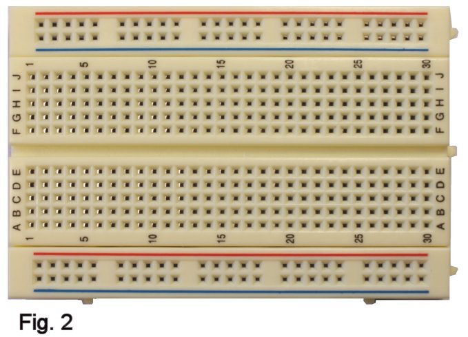
Solderless Breadboard Basics The one shown here is included in
my kits, but it is also available from numerous mail-order sources. It consists of
60 rows of five tie-points and two sets of power rails. Some sources may sell
it with only one. The vertical 5-hole rows are
connected internally, and the holes on the power rails are linked horizontally. The rows
and columns are indexed, so each hole has an alpha-numeric reference. The
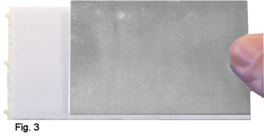
block typically has a self-adhesive back and is supplied with an aluminum back
plate for shielding. First job: Remove the protective film from the adhesive
and carefully set the back plate in place. I will refer
to holes by the references in these photos, so please buy this style of
breadboard (mine is Wish WBU-301) if you want to follow most easily.
  |
|
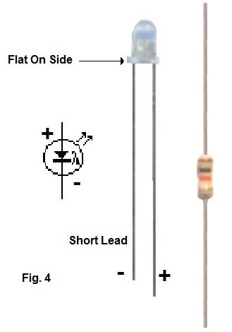
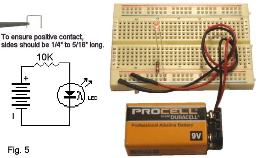
Never used this tool and need an illustration of how it works? Try this demo:
Find an LED and a 10K resistor (Brown. Black, Orange, Gold). The LED in the kit is 3mm diameter,
water-clear, high-brightness, and will light up red. If you use something
else, you can ID the negative side the same way: short lead and flat on the
side of the package (though this can be hard to see on the 3mm size).
- Insert
the LED into any two adjacent holes as shown in the right-hand pic, negative
lead to the right.
- Cut a piece of breadboard wire (usually # 20 or #22 solid)
that will span 5 holes horizontally with room left at the ends to plug in. Plug
this between the negative LED lead and the negative power rail.
- Bend the leads of the resistor to span 5 holes horizontally, trim, and
plug in between the positive LED lead and the positive power rail.
- You don't need to "dress" the leads of the battery snap as you see them
in the pic; I'll show you how to do that later. Connect the battery snap temporarily and watch the LED light. OK?
By setting this up, you have created the simple series circuit shown. If you
need to, try it in other places on the block so that you are clear about what is connected to
what.
|
|
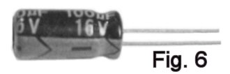
We are ready to go! Trim the leads of a 100 mf. ("microfarad")
electrolytic capacitor, following the convention of leaving 1/4" to 5/16" of
lead length for insertion in the board. Electrolytic caps are most often
polarized; on radial-lead types like this one, a band marks the negative
side (Fig. 6). Install the capacitor directly across the power rails in the
third vertical set of contacts, negative side to the negative rail (Fig. 7).
The slice of the schematic on the right shows what you have done. While the
capacitor could physically go anywhere on the power
rails, I am being very prescriptive so that your layout will be
identical to mine and so easier to debug if necessary. Follow my footsteps
(bear tracks?) and layout this time around; once you have the idea, you're free to do
whatever works.
|
   |
|
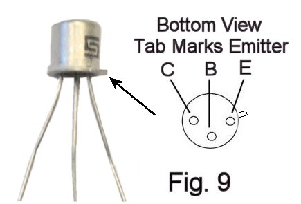
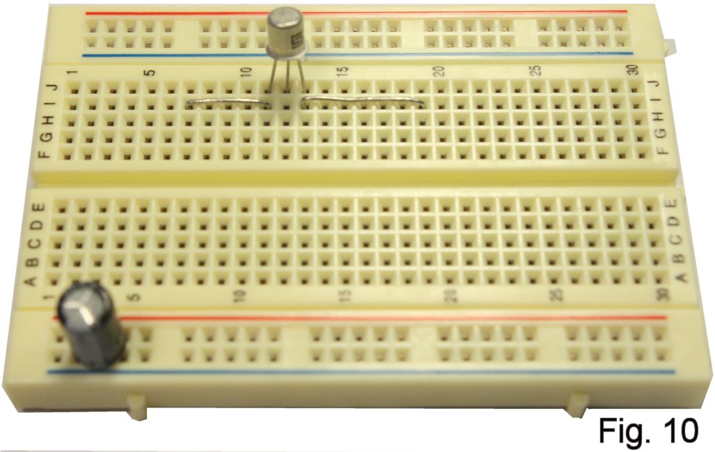
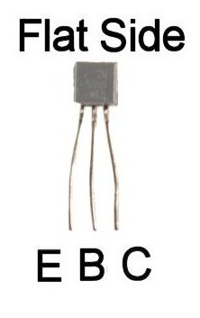
Now to install transistor Q1. The kit includes a 2N2222A; other types will work,
and I have included notes on choices at the end of this section. The transistor
comes in a metal can called a TO-18
package and has three leads: Collector, Base and Emitter,
identified as C, B and E in the schem and in Fig. 9. Plug it in with the
Collector in hole J11. Add a jumper on the Collector spanning five holes and
another on the Emitter spanning seven. We're doing this deliberately to spread
out the layout and make things more easily visible. |
|
  |
|
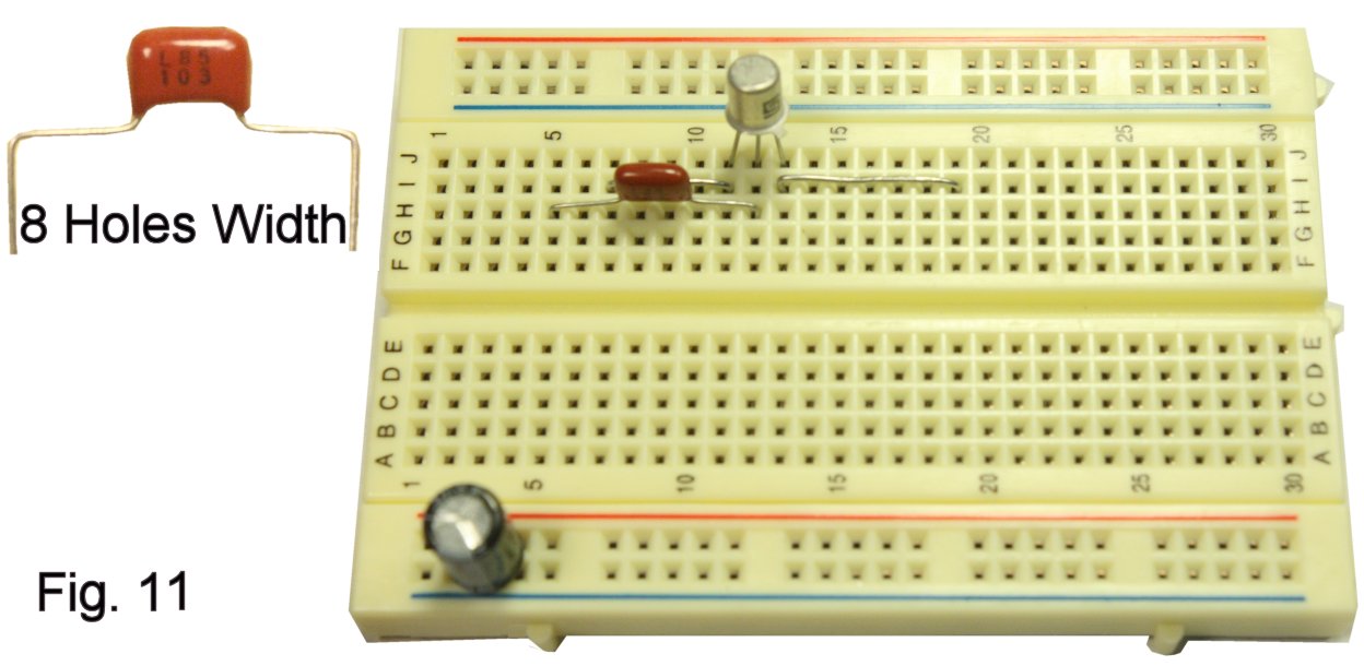
The transistor is at the center of the action in this schem, so let's first
build the input circuit on the left and then the output and tone stack on the
right. In future builds, you can choose any layout that you want, and it can be
as compact and/or chaotic as you find practical. I tell you from experience,
though, working systematically and relatively neatly makes documentation and
debugging Much easier. Find a .01 mf. polyester film capacitor (usually
labeled 103J, Fig. 11). Form leads to eight holes wide and trim. Plug this in
between locations H5 and H12. Figure 12 shows what you have connected. Got the
idea? |
 |
|
|
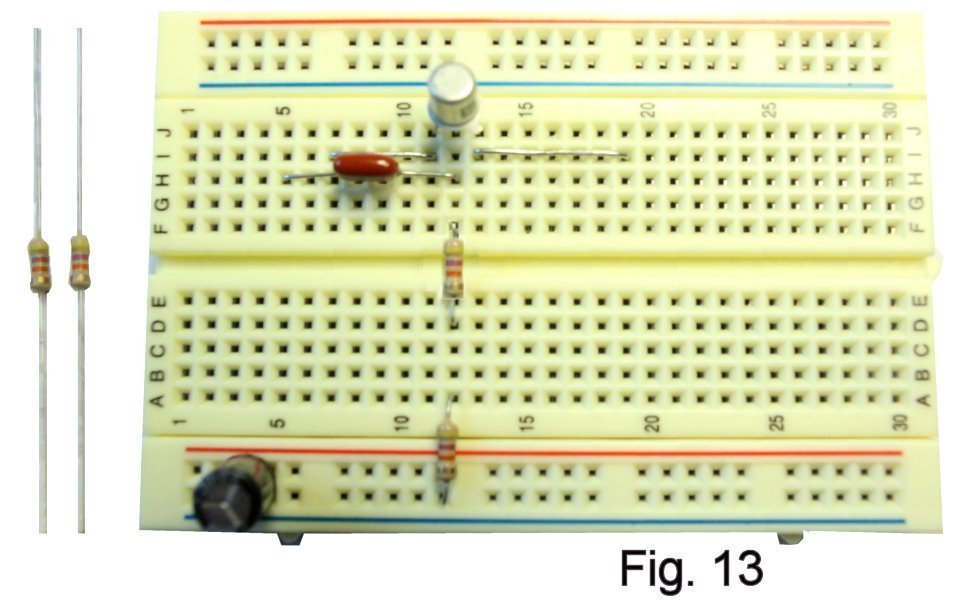
Now for a couple of the bias resistors. Find two 47K (Yellow,
Violet, Orange, Gold). Form the leads on each one to span five holes and trim. Install
starting at location F12 and continue down to the ground rail. Figure 14 shows
what is happening. |
 |
 |
|
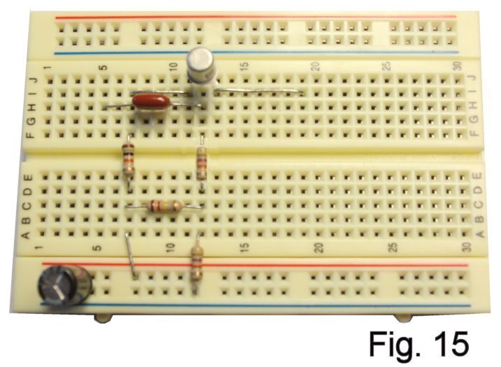
OK, form a 120K resistor (Brown, Red, Yellow, Gold) for six holes and trim. Plug
in starting at C12. It needs a connection to the positive supply rail, so form a
jumper for four pins and install. The 10K Collector load resistor is formed for
five holes and goes in starting at hole D7. Are you following in the schematic
what you are plugging into the breadboard? |
 |
 |
|
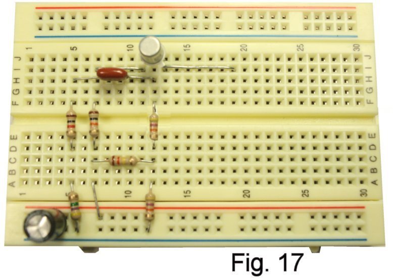
Answer to a FAQ: Notice that the physical layout on the breadboard does Not
correspond to the layout of the schem? Actually, this is the usual case;
though the components and the drawing are related, the schem and the breadboard are different media and
each has to be worked with on its own terms. Don't try to force the breadboard
layout to look like the drawing. Make the connections such that you can trace
them conveniently. Then, as you proceed, mark off in the drawing the points that
you connect on the block. Finish the input section by adding the 1K (Brown, Black, Red,
Gold) and 4.7 Meg (Yellow, Violet, Green, Gold) resistors. Both of those span 5
holes. We will add the input
jack later. |
 |
 |
|
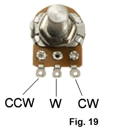
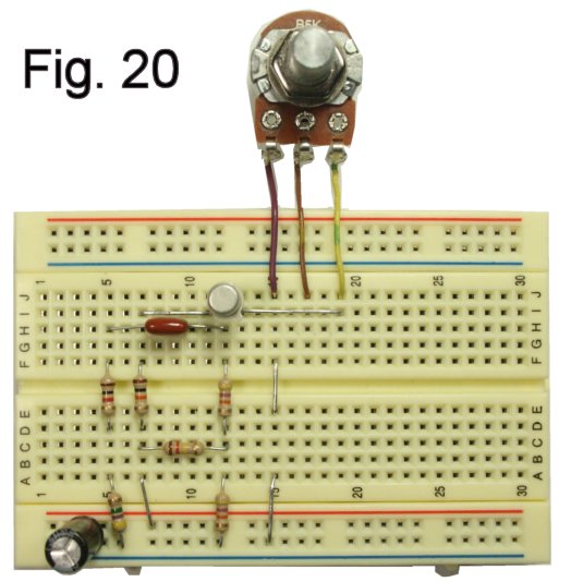
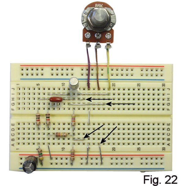
Let's start on the right-hand side of the schem by setting up and adding the
Boost pot. You want the one that is labelled "B5K", meaning 5,000 ohms, linear
taper. A typical potentiometer has three terminals: The center contact for the
moving element is called the Wiper ("W"), and the other two contacts are called
Counter-Clockwise ("CCW") and Clockwise ("CW"). Solder short lengths of
insulated breadboard wire to the terminals of the pot and install beginning from
location J15. Add two jumpers to allow the CCW terminal to reach the
ground rail. |
  |
 |
|
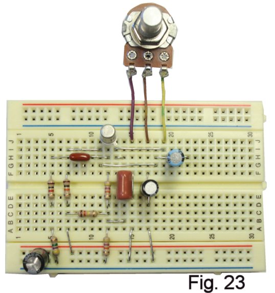
Install four jumpers as shown, and then three capacitors. The .47 mf. poly film
(labelled 474) has no polarity and so can go in either way, but the 1 mf. and 22 mf. are electrolytics; they Are polarized and must be inserted correctly.
Install the .47 mf. between E14 and F14. Form the leads of the electrolytics to
span five holes and install as shown. |
|
  |
|
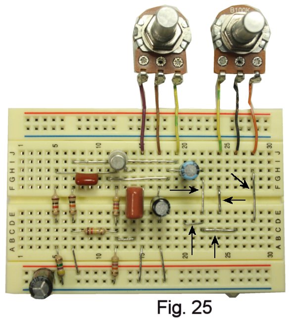
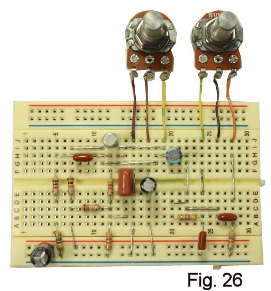
Figure 24 shows where we are to this point. Last section before installing jacks
is the tone stack. Find a 100K linear
(B100K) potentiometer and terminate it with short leads as you did the Boost
pot. Install as shown starting from location J24. Now form and install five
jumpers. |
|
  |
|
Form two 47K resistors (Yellow, Violet, Orange, Gold) to span five holes and
trim. Now find two .01 mf. (103J) capacitors. One of these is formed for five
holes; the other spans three holes, so its leads don't need to be formed.
Install the resistors and capacitors. The circuit is finished, and Figure 27
shows what you have done. |
  |
|
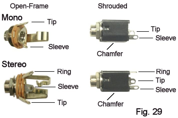
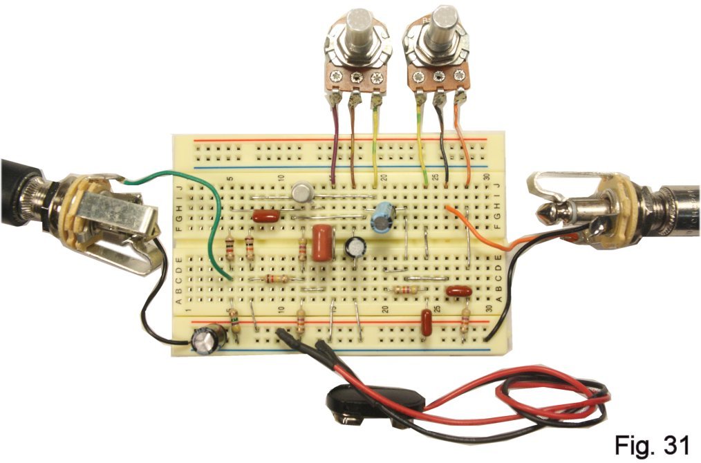
For testing, we want to install input and output jacks as shown in Figure 28.
The schematic shows mono jacks. This type has two contacts: tip and sleeve.
Figure 29 shows the relationship between the schematic symbol and the physical
items. The breadboard kit can be ordered with either the open-frame or the
shrouded jacks; the price is the same and the parts work the same way. However,
I use the shrouded style in my "deluxe" build in the Bare Box #1. If you want to
build in that platform, please order the breadboard kit with shrouded jacks. |
 |
|
|
In a typical pedal build, we use a stereo jack for the input and connect
the ring contact so as to switch battery power. (I'll discuss this further and
show how it is done when we commit to a soldered build.) To keep things simple here, we use
only the tip and sleeve. Solder short lengths of insulated wire to tip and
sleeve of each jack
and plug in as shown. Sleeve contacts both go to the negative power rail. Answer
to another FAQ: Yes, shielded cable is better because it reduces some of the
noise inherent in an open layout like this, but it is not essential for this
test. |
|
|
|
ARE YOU READY?? Connect your guitar and amp and connect a battery. Turn up the
boost
control and you should get a strong volume increase. Check out the tone control.
Doesn't work? Go back through the pics and figure out what isn't connected
right. Also be sure that:
All component values are correct
Polarities of the
electrolytic caps are observed
Transistor pinout is correct
What you see in the pics is what I did, so I am sure that your build will work if everything
matches the instructions. |
|
Troubleshooting, Transistor Choices and
Tweaks |
|
Gus's simulation for this circuit was based on a 2N2222, which has a typical
gain of 50 to 80 in the low-current mode in which we use it. In my experiments,
a transistor having a gain of 150 or more makes the booster considerably
louder and so helps compensate for the loss introduced by the tone stack--YMMV. Numerous other
common, inexpensive silicon NPN devices will also work. Obvious choices will be
BC108, 2N3904, 2N5088, 2N5089, or PN2222A. The BC108 is usually seen in a TO-18
can like the 2N2222; the last four will come in a plastic
"pill" called a TO-92 package.
For reference, Gus's voltage measurements in his simulation are: Collector
5.48, Base 2.39, Emitter 1.77. |
Here is everything needed to do all of what I have described to
this point. A kit with all of this and including open-frame jacks is SKU 0016A; with shrouded
jacks it's SKU 0016B.
I hope you enjoyed following this breadboarding tutorial. The
article that follows will re-use these parts in a soldered build on perfboard
and will cover all of the mechanics of producing a finished pedal. Comments and
technical questions are welcome here. Any problems with missing items or
shipping, please contact SBE at smallbearelec@ix.netcom.com.