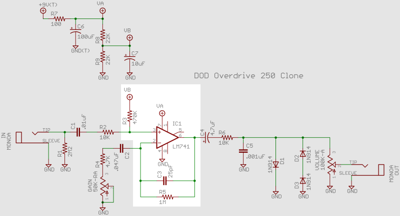
Now to the heart of the matter, let us hook up the IC, an LM741 single op amp. On the schematic, that refers to this block:
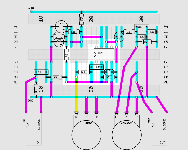
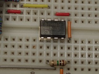
This corresponds to this part of the layout:
As for the power section, we will leave out the capacitors at first. Disconnect your battery and then
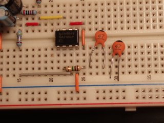
After these additions, my board looks like this:
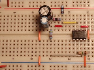
Be sure that you have oriented your IC correctly. There is usually some sort of mark (a small circle or a notch) to tell you which end has pins 1 and 8:
You can see that the yellow jumper is carrying the +9V power supply to pin 7. One of the orange jumpers is connecting pin 4 to ground. R3 and the long gray jumper are feeding a stepped down half-voltage supply to pin 3. Finally, two jumpers and R5 connect pin 6 to pin 2.
If you look at the schematic, it is as though we have treated every capacitor around the LM741 as an open circuit (or broken connection). This explains particularly why we have omitted R2; this resistor just connects to a capacitor.
Now we are ready to do a DC voltage check on the IC. After connecting the battery to the battery clip (battery now 9.45V, VA 9.38V, VB 4.68V), I measured
| pin 1 | 0 | pin 8 | 0 | pin 2 | 4.67 | pin 7 | 9.39 | pin 3 | 4.46 | pin 6 | 4.70 | pin 4 | 0 | pin 5 | 0 |
|---|
Pins 1, 5, and 8 are not connected so these voltages do not matter. As we just said, pin 7 is connected to the +9V power supply so that the 9.39V reading is close to the 9.38V that I got for VA. Pin 3 is connected to VB by a 470KΩ resistor and comes in at 4.46V, just below 4.68V. Pin 2 is just below pin 6, 4.67V versus, 4.70V because they are separated by a 1MΩ resistor. Without talking about op amps, we have no justification for the levels of these last two pins.
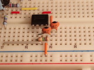
There is only one capacitor to add for this section and that is C3, the capacitor in the feedback loop. If you have a 25pF capacitor, then just put its leads in B22 and B25. I did not have a capacitor of that value on hand. However, I did have two 47pF capacitors:
I can use these two capacitors instead because if two capacitors are in series, then their combined capacitance is
(C1 × C2)/(C1 + C2)
where C1 and C2 are the capacitances. If C1 = C2 then this simplifies to C1/2, half the original values. So my 47pF capacitors, in series, make a 23.5pF capacitor. Given that a 25pF capacitor could actually be 23.5pF (with a tolerance of 10%), my build should be fine. Here is how I installed them in series: