This project is a walk-through tutorial for building an IC-based overdrive like the DOD Overdrive 250 on a breadboard. I will build in steps and explain the design of the circuit as I go. Thanks go to idlechatterbox for beta testing some of this material. Any mistakes are mine. I am looking forward to getting help with this from everyone on the forum who wants to participate.
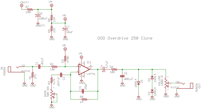
The online source for the schematic that we will follow is http://generalguitargadgets.com or http://tonepad.com/. Here is the schematic for this project:
This schematic shows a common organization of the circuit where the power section is shown separately from the rest. Here the power section is the group of transistors and capacitors in the upper left-hand corner.
Ground connections appear as triangles pointing downward. There are several supply voltages: +9V, VA, and VB. Each is represented by a circle with a plus sign in it, denoting a positive voltage. On other schematics you may see other voltage symbols such as upward pointing arrows or triangles of various kinds. Using these symbols for different voltage supplies can make the schematic for the circuit simpler. In this case, because VA and VB each connect to only one location, there isn't any simplification.
The heart of this circuit is easy to spot: it's IC1, the LM741 single op amp sitting smack in the middle of the schematic. Op amps are drawn as triangles with inputs at the plus and minus signs on one side and a single output at the opposite corner. In this case, the audio signal goes into pin 3 at the plus sign and out pin 6. There's a loop back from the output pin to pin 2 called the feedback loop. This loop is responsible for the amplification of the audio signal. As a result, the feedback loop can also yield some of the overdrive (or distortion).
On its way out of the circuit, you can see that the audio signal passes by some diodes that are also connected to ground. These are often called diode clippers and they contribute another source of distortion.
The rest of the circuit contains capacitors and resistors that help make all of this work together, setting signal levels for various frequencies of alternating current.
The plan is to construct this circuit on a breadboard, starting with the power section. Then we will add the IC followed by the input and output so that we can try the circuit without the diode clippers. Finally, we will complete the circuit by adding the diode clippers.
Here is a list of the parts shown on the schematic. You will need these to make the breadboard layout. Of course, you will also need a breadboard and solid core hook up wire or premade jumpers. Vendors sometimes bundle jumpers with their breadboards.
Part Value
C1 .01uF
C2 .047uF
C3 25pF
C4 4.7uF
C5 .001uF
C6 100uF
C7 10uF
D1 1N914
D2 1N914
D3 1N914
R1 2M2 or 2.2M
R2 10K
R3 470K
R4 4.7K
R5 1M
R6 10K
R7 100
R8 22K
R9 22K
GAIN 50K-RA
VOLUME 100K-A
IC1 LM741
Also: 2 mono jacks
1 9V battery clip
1 9V battery
The 50K pot for Gain is marked as ``RA'' which stands for reverse audio. For this project, any 50K pot will be fine. The same goes for the 100K pot---audio or linear will be fine.
Indeed, in my actual build I am going to make several substitions to parts on this list because I did not have the exact component values at hand. This happens all the time with building stompbox circuits, and especially with breadboard builds. The idea is to build a working circuit and to experiment. That is what breadboards are all about. As an example, I did not have any 22K resistors when I did this, so I just used a pair of 20K resistors. Strictly speaking, we don't even need R1, the 2.2M resistor connected to the input. I will discuss these changes to the schematic later.
If you are new to breadboards, here is one online introduction that is on my website: tools: breadboard.
Here is a plan for our breadboard layout and a photograph of a partial layout:
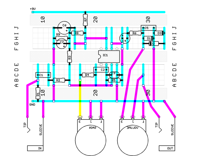
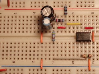
You can see the IC in both with pin 1 in column 21 and row E. R7 is at the top in column 18. C6 (the large black electrolytic capacitor) and C7 (the smaller blue electrolytic) are also plain to see, but R9 is hidden beneath C7. By the way, you don't have to follow my postitions exactly as long as you make the same connections. If you run into trouble, perhaps then you should pull everything apart and try to reproduce my build exactly.
On the map there are thick pink lines that represent jumpers. These are shown in the photograph as red, yellow, orange, and gray jumper wires. The color coding of the jumpers corresponds to premade lengths that you can buy. Cutting your own is just as good.
On the map there are also thick blue vertical lines that represent connections available in the breadboard. Five adjacent holes in the same numbered column are connected. To give an example, look at column 18 for rows G, H, I, and J. In the diagram, R7, R8, and two pink jumpers connect together through the blue vertical line for those rows of column 18. You can see the same arrangement in the photograph. R7 has one lead stuck into J18 (row J and column 18). That lead is connected to the lead of R8 that is in I18, and the yellow jumper lead in H18, and the red jumper lead in G18.
The thick blue horizontal lines along the top and bottom of the map are power rails. We are going to use the top one, marked with a red line on the actual breadboard, for +9V from a battery. We are going to use the bottom one, marked with a blue line on the actual breadboard for ground. So R7 is also connected to +9V. One of the leads of C7 is connected to ground, because the two orange jumpers beneath C7 in the photograph connect to the ground rail through row 12.
Unlike the other groups of 5 holes, the power rails are connected horizontally across the rows of 5 holes. So, in the photograph, R7 is connected to the hook up wire that is stuck into the first power rail hole in the upper left-hand corner.
Note: On some breadboards, these power rails only run for half of the board and you need to put in jumpers if you want to connect them all the way across.