- Welcome to DIYstompboxes.com.

DIYstompboxes.com
News:
SMF for DIYStompboxes.com!
Recent posts
#41
Building your own stompbox / Re: Dist+ or DOD 250 or Ross D...
Last post by zbt - Yesterday at 04:36:27 PMI always think about this, when I was little I went to an exhibition, and entered a small room with 4 little speakers
The sound was very big, I was confused in my heart and said how could that be?
It looks exactly like this

At that time I only saw the 4 small monitor speakers, the big one
which is like an invisible subwoofer, after I read in a magazine article about how it works. If I'm not mistaken, it's like an organ pipe, resonating at 45Hz and 90Hz. maybe for resonance too,
that's why I wondered if it wasn't like a small lizard that looked big.
but I think it seems strange, so we might as well just ask them what it's for
Frankly, I don't know, the lesson for me is that I should ask directly
before I forget, (many circuit so short time)

For LM308 there transistor set like diode clamp for 0.7V

And OP07 would be 1.4V maybe different from LM308 cause it sound a bit bright

so for LM741 is it possible to make slew it like this?
anyone know how to calculate the value for the capacitor?


while NE5534 same as LM308, it could be the secret of Uncle Jimi Pink Clipper
or Pink Triple Clipper
reminds me of

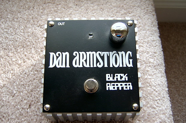
Black Repper, Yellow Humper, Green Ringer, Pink Clipper, Blue Clipper, Red Ranger
lets make two other hero Purple Peaker and Orange Squeezer
Introducing Dan Armstrong Eight Rangers
We should build it for kids today, hopefully they can learn guitar while they young.
does anyone know the schematic for the black one
The sound was very big, I was confused in my heart and said how could that be?
It looks exactly like this
At that time I only saw the 4 small monitor speakers, the big one
which is like an invisible subwoofer, after I read in a magazine article about how it works. If I'm not mistaken, it's like an organ pipe, resonating at 45Hz and 90Hz. maybe for resonance too,
that's why I wondered if it wasn't like a small lizard that looked big.
but I think it seems strange, so we might as well just ask them what it's for
Frankly, I don't know, the lesson for me is that I should ask directly
before I forget, (many circuit so short time)
For LM308 there transistor set like diode clamp for 0.7V
And OP07 would be 1.4V maybe different from LM308 cause it sound a bit bright
so for LM741 is it possible to make slew it like this?
anyone know how to calculate the value for the capacitor?
while NE5534 same as LM308, it could be the secret of Uncle Jimi Pink Clipper
or Pink Triple Clipper
reminds me of
Black Repper, Yellow Humper, Green Ringer, Pink Clipper, Blue Clipper, Red Ranger
lets make two other hero Purple Peaker and Orange Squeezer
Introducing Dan Armstrong Eight Rangers
We should build it for kids today, hopefully they can learn guitar while they young.
does anyone know the schematic for the black one
#42
Building your own stompbox / Re: Little Gem Mods
Last post by Microtone - Yesterday at 03:55:13 PMQuote from: Matthew Sanford on Yesterday at 01:07:06 PMThe input potential meter lowers the signal so then it's not as loud because it has to amplify it a lot due to how an LM 386 is. For the gain you might wanna look up the Ruby amp schematic and follow how they handle pins one and eight, or look at the LM 386 data sheet for the info.Thanks for the advice. So, I could potenti(ometer)ally put a variable resistor at the start and find a good resistance that works for most guitar-based situations and then just add a single input resistor of that value at the start of the circuit?
#43
Building your own stompbox / Re: VCA based Guitar Volume Co...
Last post by ElectricDruid - Yesterday at 03:08:49 PMI don't agree that 2180 and 2164 are difficult to use. They're pretty straight forward. The '2180 even has two control inputs, so you can decide if you want negative or postive control voltage - you can pick whichever suits the situation. For volume control applications the exponential mV/dB response is helpful, whereas the LM13700 is linear which is not so good.
And if you've already *got* the 2180, then yes, use it!
And if you've already *got* the 2180, then yes, use it!
#44
Building your own stompbox / Re: FORUM downtime - April 15t...
Last post by aron - Yesterday at 02:35:51 PMIt does seem pretty fast.
#45
Building your own stompbox / Re: FORUM downtime - April 15t...
Last post by stallik - Yesterday at 02:17:31 PMAnd it's working faster than a very fast thing 
#46
Building your own stompbox / Re: Electronics for Guitarists...
Last post by Electronics 4 Guitarists - Yesterday at 02:00:32 PMNot sure what happened to my YouTube link so I'll try again here.
https://youtube.com/@Electronics4Guitar?si=TJY01cCtEQqAD-cf
https://youtube.com/@Electronics4Guitar?si=TJY01cCtEQqAD-cf
#47
Building your own stompbox / Electronics for Guitarists
Last post by Electronics 4 Guitarists - Yesterday at 01:52:42 PMHey guys. I'm the author of a book "Electronics for Guitarists" that's been out for a few years and I recently started a YouTube channel related to the book. So far I've posted a lot of tutorials on basic circuit theory and transistor circuit analysis, I'm planning to post a lot of content covering effect design, vacuum tube amp design etc. It's pretty detailed and there's no fluff or subjective opinions. Down and dirty analog circuit analysis and design. If anyone is interested in checking it out (and hopefully subscribing), here's the link. Thanks!!
https://l.facebook.com/l.php?u=https%3A%2F%2Fyoutube.com%2F%40Electronics4Guitar%3Fsi%3Dd-uSr4vpD9gCdm_s%26fbclid%3DIwZXh0bgNhZW0CMTAAAR0GQuEvxcXwWPjwwjruzeQSkHsiQNXC6F1PM_9ftoXKBGrzf3rEyqs32Sk_aem_AWKHKbyBo9ENacI5UsVirNe-F-Mm4mcuxAzmb20ldyTuWaXX8LiOj1vmH_en8-vufnlumH_DBg2sW9RXEtZ2bfan&h=AT3PfdAEpSSJlXCsUn8oOci6FcSC1g4XTWuePciuSM9p-Y7Lj8ZLtAV5_xf5CrtRxyusVSkOXR6iobVrakl1ixibiT_nkx4QBjCSJ6SCJAiBku8-ecKfgGYiV5NwK5r5cg&__tn__=R]-R&c
https://l.facebook.com/l.php?u=https%3A%2F%2Fyoutube.com%2F%40Electronics4Guitar%3Fsi%3Dd-uSr4vpD9gCdm_s%26fbclid%3DIwZXh0bgNhZW0CMTAAAR0GQuEvxcXwWPjwwjruzeQSkHsiQNXC6F1PM_9ftoXKBGrzf3rEyqs32Sk_aem_AWKHKbyBo9ENacI5UsVirNe-F-Mm4mcuxAzmb20ldyTuWaXX8LiOj1vmH_en8-vufnlumH_DBg2sW9RXEtZ2bfan&h=AT3PfdAEpSSJlXCsUn8oOci6FcSC1g4XTWuePciuSM9p-Y7Lj8ZLtAV5_xf5CrtRxyusVSkOXR6iobVrakl1ixibiT_nkx4QBjCSJ6SCJAiBku8-ecKfgGYiV5NwK5r5cg&__tn__=R]-R&c
- =AT04Y0QIAqRkNpsOPUR48UIMggGat5b4iCdKE6YTg5C9hZkthYhn0_95_2nRlX2zObmyoAD2ZPZWyHQPt1guzXJs6JTj6eSjNnTcC3XbmMnsZiUi8mQkKi-AjShADkyXmFHRkbYDJDCVtIZO_uknlIztQ30ySoi0oNe4JpiGC6whQJsn2LEQdvZeBHWhNzaUMAjpvyX89-8ZSGgmZ8s1SeWy28i4VBegcUw4
#48
Building your own stompbox / Re: Deadend FX Mangel Wurzel n...
Last post by PRR - Yesterday at 01:37:09 PMhttps://drive.usercontent.google.com/download?id=1OpvxwDCM6n1V6RT3K5LvCE-sm3y7ayhj&export=download&authuser=0
> output B has noticeably more output/ gain than output A
They are the same circuit on the same signal. One of the output stages IC2_A or IC2_B has to be wrong. What's different?
> output B has noticeably more output/ gain than output A
They are the same circuit on the same signal. One of the output stages IC2_A or IC2_B has to be wrong. What's different?
#49
Building your own stompbox / Re: FORUM downtime - April 15t...
Last post by aron - Yesterday at 01:32:30 PMNever mind. I guess the forum is already live and working.
#50
Building your own stompbox / Re: FORUM downtime - April 15t...
Last post by aron - Yesterday at 01:25:28 PMGoing to switch the IP today. Forum may go down.