- Welcome to DIYstompboxes.com.

DIYstompboxes.com
News:
SMF for DIYStompboxes.com!
Recent posts
#71
Building your own stompbox / Re: Help with MicroControllers
Last post by Box_Stuffer - April 23, 2024, 08:17:12 PMQuote from: PRR on April 23, 2024, 06:55:39 PMhttps://microkits.net/products/microkits-theremin-kit
Circuit is in the "Read Booklet Online":
I think the basic instrument is the '556. The 556 is a dual timer, which can be oscillators. Since there are no explicit timing caps, I bet they sing 1/(3pFd*68000) or 5 MEGAhertz. The 3pFd and the 5MHz is more-or-less depending on hand position.
We don't call 5MHz "music" but if divided by about 10,000 it would be 500Hz, midscale of guitar or piano.
A 'tachometer' function on the left-hand oscillator would turn frequency to amplitude which could modulate a Volume.
The MICRO "could" also monitor for the lowest capacitance and set a standard frequncy (self-tune) or mute/clamp extremes of volume (to hide the low-pitch growlll when the piece is finished).
So they have replaced a LOT of circuitry with programming. That saves lots of labor when you make a million of them. But it may be a LOT of brain-labor to create that programming (beyond my vague verbal sketch).
> the most simple circuit
Because they hid the complexity. Not to be secretive, just to have fun and profit.
So does that mean the MCU needs to be programmed somehow to work properly?
#72
Building your own stompbox / Re: Help with MicroControllers
Last post by PRR - April 23, 2024, 06:55:39 PMhttps://microkits.net/products/microkits-theremin-kit
Circuit is in the "Read Booklet Online":
I think the basic instrument is the '556. The 556 is a dual timer, which can be oscillators. Since there are no explicit timing caps, I bet they sing 1/(3pFd*68000) or 5 MEGAhertz. The 3pFd and the 5MHz is more-or-less depending on hand position.
We don't call 5MHz "music" but if divided by about 10,000 it would be 500Hz, midscale of guitar or piano.
A 'tachometer' function on the left-hand oscillator would turn frequency to amplitude which could modulate a Volume.
The MICRO "could" also monitor for the lowest capacitance and set a standard frequncy (self-tune) or mute/clamp extremes of volume (to hide the low-pitch growlll when the piece is finished).
So they have replaced a LOT of circuitry with programming. That saves lots of labor when you make a million of them. But it may be a LOT of brain-labor to create that programming (beyond my vague verbal sketch).
> the most simple circuit
Because they hid the complexity. Not to be secretive, just to have fun and profit.
#73
Building your own stompbox / Help with MicroControllers
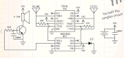
Last post by Box_Stuffer - April 23, 2024, 06:09:55 PMI have been searching for the most simple circuit for a functional theramin and I came across the Microkits theramin. They are very vague about the specifics of their ICs and the ones they include in the kit are blank with bug eyes (to appeal to kids) , but after a lot of searching I discovered that they are a 556 timer and a CY8C24123A-24PXI Multicontroller - which I can not find anywhere. I do have a few ATTINY13A that I got off of ebay. The resistors are 47K and 68K.
Here is a shot of the circuit on a breadboard from the instruction book.

Here is the pinout of the CY8C24123A-24PXI that they use and I can not get.

and this is the pinout of the ATTINY13A that I have.

Is there a way to make it work? I don't have any experience with MCUs.
Here is a shot of the circuit on a breadboard from the instruction book.
Here is the pinout of the CY8C24123A-24PXI that they use and I can not get.
and this is the pinout of the ATTINY13A that I have.
Is there a way to make it work? I don't have any experience with MCUs.
#74
Building your own stompbox / Re: Uncompensated op-amps
Last post by Rob Strand - April 23, 2024, 05:46:43 PMQuote from: David on February 23, 2004, 03:39:31 PMI'm kind of looking at the redraw Joel Purkiss posted of Anderton's compressor. It looks like a good candidate, especially since I have an idle CLM-6000 that been waiting for something to do for 21 years! Here's my question: the circuit calls for an uncompensated op-amp, like a 201, 301, etc. Now, I can get some 301's, but I'm wondering what's so special about them. Couldn't I sub a 741 or a 5534 for a 301?
It's an uncompensated opamp but it has a compensation cap connected which then turns it into a compensated amplifier! You can use any opamp, it will work. Just leave off the compensation cap (pins 1 and 8 ).
#75
Building your own stompbox / Re: Suggestions about circuit ...
Last post by GibsonGM - April 23, 2024, 05:45:34 PMOne could consider the JFET splitter to be a wonderful introduction to the world of FETs 
Before you know it, OP might be back asking how to match them for a phaser...
I picked up many 2N5457's a long time ago, so I look for places to use them.
Before you know it, OP might be back asking how to match them for a phaser...
I picked up many 2N5457's a long time ago, so I look for places to use them.
#76
Building your own stompbox / Re: Suggestions about circuit ...
Last post by antonis - April 23, 2024, 04:20:25 PMWhat lazy Druid proposed you : 
(U1A & B dublicated for 4 splitted outputs..)

P.S.1
What Sir Mike proposed is equivalently good but I don't know if you wish to mess with those nasty

 JFETS..
P.S.2
Welcome, also..
(U1A & B dublicated for 4 splitted outputs..)
P.S.1
What Sir Mike proposed is equivalently good but I don't know if you wish to mess with those nasty
JFETS.. P.S.2
Welcome, also..
#77
Building your own stompbox / Re: Resonant Filters
Last post by ElectricDruid - April 23, 2024, 02:37:59 PMQuote from: Gobotak on April 23, 2024, 12:30:47 PMI was thinking the VCA itself was not inverting from page 4 of the ssi2164 datasheet:
https://www.soundsemiconductor.com/downloads/ssi2164datasheet.pdf
"For audio level applications where the VCA is used only to vary the signal level (e.g., mixer automation, synthesizer VCA module, etc) the combination of SSI2164 VCA and
opamp (Figure 1) produces an output whose phase is inverted."
Am I misunderstanding this?
No, I've checked and you're right and I'm wrong. Sorry about that. The VCA itself doesn't invert, but the whole thing does. I had it back-to-front.
QuoteRegarding phase shift, would the phase shift of a high pass filter be 45 degrees or 90 degrees?45 degrees at the cutoff freq.
QuoteThe document states that single pole filter stages are 45 and an all pass is 90. A high pass and all pass are identical except for one resistor being halved.That's true, but that one resistor value makes a big difference to the overall frequency response, as well as the phase!
Perhaps a more intuitive way of thinking of it is that halving that value doubles the amount of that signal in the mixture. That makes the significant change a lot more comprehensible (to me, at least
 ).
). #78
Building your own stompbox / Re: Resonant Filters
Last post by Gobotak - April 23, 2024, 12:30:47 PMThanks for the help and suggestions!
https://www.soundsemiconductor.com/downloads/ssi2164datasheet.pdf
"For audio level applications where the VCA is used only to vary the signal level (e.g., mixer automation, synthesizer VCA module, etc) the combination of SSI2164 VCA and
opamp (Figure 1) produces an output whose phase is inverted."
Am I misunderstanding this?
Regarding phase shift, would the phase shift of a high pass filter be 45 degrees or 90 degrees? The document states that single pole filter stages are 45 and an all pass is 90. A high pass and all pass are identical except for one resistor being halved.
Quote from: ElectricDruid on April 22, 2024, 04:33:20 PMIt looks a lot like you've been reading the SSI application note about designing analog filters with the SSI2164:Yep! It has been a great resource for learning how to set up filters with this chip.
https://www.soundsemiconductor.com/downloads/AN701.pdf
...and quite right too! It's a fantastic document! It's pretty much a summary of about 30 years of synth filter history in about as many pages.
QuoteI notice you've halved the value of your R56 feedback resistor though. What's the purpose of that?I copied from a different schematic and forgot to change the value. Whoops.
QuoteNo. The *VCA* itself is inverting, but it's followed by an I-to-V op-amp stage (U4.2 in your lowpass schematic) which is also inverting, so there's no net inversion through the typical whole 2164 VCA schematic.I was thinking the VCA itself was not inverting from page 4 of the ssi2164 datasheet:
https://www.soundsemiconductor.com/downloads/ssi2164datasheet.pdf
"For audio level applications where the VCA is used only to vary the signal level (e.g., mixer automation, synthesizer VCA module, etc) the combination of SSI2164 VCA and
opamp (Figure 1) produces an output whose phase is inverted."
Am I misunderstanding this?
Regarding phase shift, would the phase shift of a high pass filter be 45 degrees or 90 degrees? The document states that single pole filter stages are 45 and an all pass is 90. A high pass and all pass are identical except for one resistor being halved.
#79
Building your own stompbox / Re: Christine!!!
Last post by Matthew Sanford - April 23, 2024, 12:06:51 PMInteresting. On the other hand I'd read both resistances (Vss & Vcc) help create the distortion characteristics for those 4049 chips (not 4066, what crazy person would say that?). It makes me wonder if how much it's held off the rails affects which guitars work well with it? I'm probably reading too much into that, but after I finish boxing/testing my filter and correcting errors on my StompLFO, gotta clean/organize lab then set it back up on a breadboard to get my friends LP plugged in. I think I'll do a pot on the Vcc to see if balancing between rails helps, with:without input buffer and as variable gain reducer to see if anything makes it work for the LP.
Watching that Insano pedal video again not sure if they have it done the same, with all the resistance on the power part they still had good sustain, for mine set that way it's maybe a second before cutting low
Watching that Insano pedal video again not sure if they have it done the same, with all the resistance on the power part they still had good sustain, for mine set that way it's maybe a second before cutting low
#80
Building your own stompbox / Re: Uncompensated op-amps
Last post by antonis - April 23, 2024, 11:13:23 AMQuote from: duck_arse on April 23, 2024, 10:35:31 AMand a welcome, Antonis?
Definitely, NO...!!