Although Ken has passed away, we can still enjoy some of the articles he wrote.
Ken Fischer articles
1 Reply
Although Ken has passed away, we can still enjoy some of the articles he wrote.
I found a place that makes replacement turret and eyelet boards for Fender amps! Should fix any conductive boards that are in old amps.
Vintage Gear, a store in Los Angeles on Hollywood has amazing vintage pedals. All at a very high price of course. But if you can afford it, that Colorsound can be yours! I’ve never seen so many Jordan Boss Tones in one place!
I was recently hunting for a combo cabinet so that I could put my 6G6-B Blonde Bassman into a 1X12 combo situation. Here are some of the options I found:
Here is a sound sample comparing the 2 Bill Lawrence pickups. L200 vs. L280s
L200 is the first 16 bars. Then the 280. At then end its 200 followed by 280.
Your DIY pedal can end up sounding like what YOU want. Here are links to different sites with DIY samples.
Check out GFR’s Site on effects. It’s been around for a while and there’s lots of very useful info on this page.
Most of my guitars are equipped with Bill Lawrence pickups. Whether it’s the L90 or L280s or the new L200 or L298, I love the clarity and the output of the Bill Lawrence pickups!
Check out the site of this great sounding band. Marty is a frequent member of DIYstompboxes.com and he uses his DIY pedals with The Decoders. While you’re there, pick up the CD!
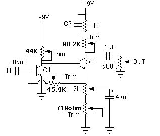
Hand wiring a circuit can be as simple as placing components on the perfboard almost exactly as drawn in the schematic. For example, take the Hornet, my Fuzz Face clone:
Here is the schematic:
Here is the parts layout as placed on perfboard below (you are looking through the perfboard as seen through the BOTTOM of the board – copper side). Component side is the top.
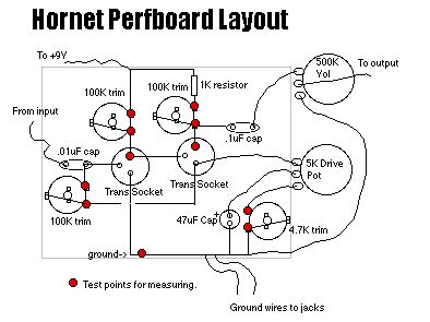
Notice how similar they look? It is really true that if you connect the components together exactly as shown on a known good schematic and use the correct parts, the circuit will work. You can do this for a great many schematics. Simply place them on the perfboard almost exactly as drawn in the schematic. In the above example, the 100K trim connected to the .01uF cap has a lead that connects to the emitter of the 2nd transistor. Since it must not touch the emitter of the first transistor, simply run the wire on the TOP of the perfboard then run it back under to touch the transistor socket’s lead.
Note that we are looking at the BOTTOM of the board as if the board was invisible and we could see right through it. As you build more and more projects, you will get used to looking at the board and the schematic and “visualizing” right through it. The leads that stick out of the bottom of the board will be your visual clues for placement. You simply place the components into the perfboard holes, then bend leads on the copper side to make connections. The perfboard copper can be used to solder onto the pads and provides stability.
The red dots are test points for setting up the trim pots. To set up a trim pot, you touch the black probe to a red dot on the trim and the red probe to the other point. Then turn the trim until you get close to the values shown on the schematic.
To test the transistor voltages at the collectors, connect the red probe to the red dot on the transistor socket and the black probe to ground.
More rough layouts
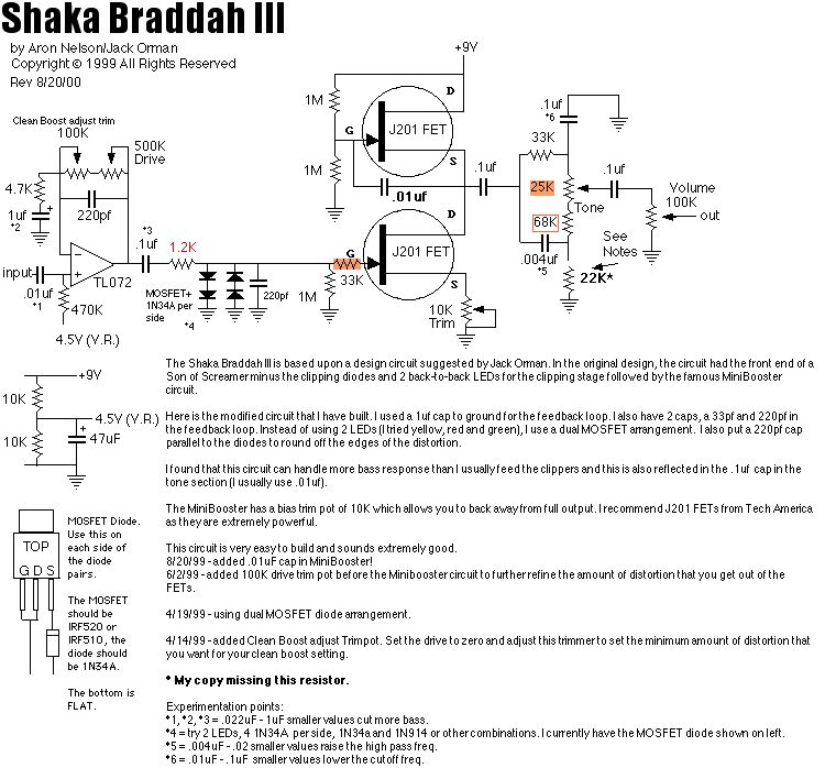
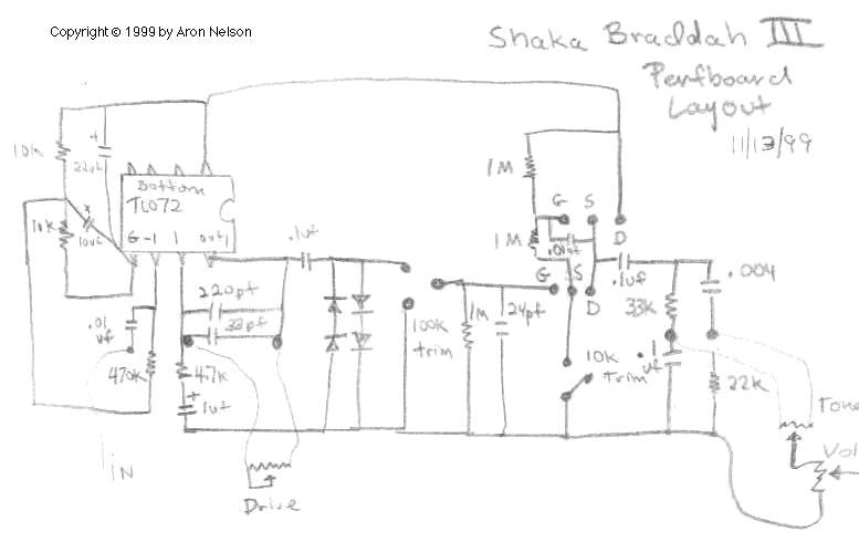
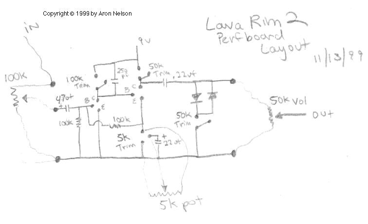
Take a look at these other rough layouts for perfboard. Basically you start from the schematic, rough sketch a layout on paper, then follow that layout on your perfboard. Don’t forget that you can stand the resistors on end instead of having them flat on the perfboard. This saves a tremendous amount of space.
| Shaka III schematic | Shaka III rough layout |
| Lava Rim 2 schematic | Lava Rim 2 rough layout |
See how similar the perfboard layout can be to the schematic? Practice, and after a while, you will be able to layout and build a prototype perfboard circuit in very short time.
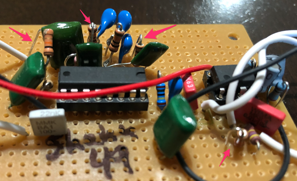
Here is an example of components on perfboard. The connections in colors (red, green, blue) are the connections that can be created by using resistor/capacitor/wires, to create the connections. (Cut off a piece of resistor lead and use that as a connection).


You can also stand resistors up so that they take up less space and even connect two components together like a resistor and capacitor so they use only 2 holes.