
OK, we are going to wire up our diode-compression op amp circuit.
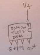
Excited? You should be. You are moments away from a great sounding mod! This drop-in replacement for an op amp is a cool circuit. Since it is an implementation of a single op amp, I'm going to wire it as a replacement for one of the two op amps in a dual op amp like the TL072 or RC4558. I typically use dual op amps, but only use "one side" of them. Here's how I wired mine.
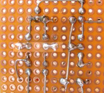
First we will wire the power line. Just like a component, put the wire through the hole and solder.
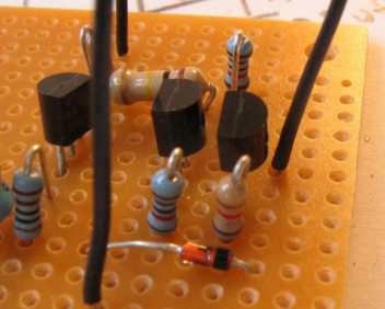
Here's the top view.

I'm going to wire the ground of the circuit now. Since I have already connected all of the ground points together in this circuit, it's an easy wire. Here it is, soldered.

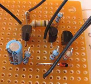
The rest is the same. I follow with the non-inverted input, then inverted input wires.
Here is the positive input wire soldered and the inverted input ready to be soldered.

Both input wires soldered.
Here's a top view.

Output wire is next.

Done with wiring the board!
Next I wire a DIP 8 socket so I can stick it where the real op amp is currently. In this case I cut a bigger DIP socket to be a DIP 8. I connect the wires referencing the standard dual op amp pinout.

OK, plug in and enjoy!
Thank you Joe Davisson!