Permission is granted to link to the schematics on this page however I do not extend permission to place copies of the schematics stored on this site on other sites. In other words, you can link, but don’t download and place them on your server and show them as yours.
Before you go wild downloading these links and buying parts for the schematics listed below, there are a few things you should know.
- If you don’t feel like reading yourself or helping yourself, you shouldn’t pursue building your own boxes. Read all the links you can before asking questions.
- Some schematics on the Internet have mistakes. There is no way to know. I got caught by one of these and it cost me a lot of time before I realized that the schematic was incorrect. You can protect yourself from this by purchasing a solderless breadboard (also known as prototype board). These types of boards make it easy to prototype a circuit and see if it works and how it sounds before you commit to putting it on a perfboard where changes are not as easy to make. Unfortunately you still have to buy the parts to prototype it even if it’s a bad schematic 🙁
- Building a complete effect (with box, stomp switch) costs money. The components are cheap but the box, stomp switch, pots, are expensive. If possible, go mail order for these parts. In many cases you may be paying MORE than if you had purchased the unit.
- YOU WILL MAKE MISTAKES. Prepare to take some time to debug your circuit. If you’re the type that’s patient and can use this as a learning experience, great! If you don’t like this sort of thing, don’t do it. Buy ready-made effects. Read R.G. Keen’s Effect FAQ for more caveats.
- Your stompbox could sound different from the original, especially if you don’t use the recommended parts or values. This is especially important when using certain types of transistors such as FETs. Many times, even the brand and type matters, especially for capacitors!
- Just purchase some of them, if you look at the schematic and it looks intensive, then perhaps you should just buy the pedal. This goes for most delay type pedals unless you have a PCB. Hand-wiring is just not appropriate for complex circuits. There is a coolness factor that is the box and name alone. Another reason is that some of these manufacturers are really cool guys and care about their pedals. Many hand-made pedals are simply great and there is a reason why they are so popular. If you value your time and really can’t afford to waste a lot of it, consider the reasonable prices of hand-made pedals that are popular and selling. After you get past some of your mistakes and buy a bunch of parts, $175 for a hand-wired pedal doesn’t seem bad at all 🙂
I encourage you to purchase pedals in production. If it’s currently in production and you can afford it, buy it.
Selected Stompbox Schematics
Note that not all of these schematics are guaranteed to work. Some may be completely wrong. I have added notes in red to the schematics believed to have errors. Items confirmed by me or others have an OK! in green. This is not meant to discourage you from trying the other schematics out, just that I haven’t heard anything about them.
In very general terms, I would say that probably every schematic on Jack Orman’s (AMZ) page is fine; Keen’s (GEO) page is excellent as well.
The schematics are listed by manufacturer or type or designer with the name of the stompbox and the web site that it is located at. I encourage you to look through these great websites and learn more from the excellent articles on them.
About the files:
Most are .gif or .jpg and can be viewed right away. The files with .pdf at the end need Adobe Acrobat Reader. The files with .ps are Postscript files and need a Postscript Viewer. The files with .ps.Z are compressed (I forget the format… tar?) they need to be uncompressed then viewed with the Posctscript viewer. Stuffit Expander should work on these files.
A/B SwitchBoxes
Ampeg
Arbiter
- Fuzz Face (Guitar Related Circuits) OK! Here is an article on how to test those germaniums for use in the Fuzz Face (GEO)
- Technology of the Fuzz Face – (GEO) Excellent article about the Fuzz Face.
- Fuzz Face 99 – Check out this mutant. Updated 1/6/01
Aron Nelson – Circuit-Ware – not shareware, but something like it.
- Lava Rim 2 – OK! The Lava Rim revisited. I realized the original Lava Rim sounds better than the Lava Rim+! Here are my changes after a year. I think it sounds great! Sound samples available.
Key points about the Lava Rim 2, uses cheap readily available 2N3904 transistors, sounds good and can get creamy – slightly compressed tones with the drive and input pot set low as well as nasty heavier types of distortion. It’s also very easy to build and easily adapts to germanium NPN transistors; the trimpots really allow you to dial in a very good tone. 11/29/99 – The Lava Rim 2 is a versatile circuit! You can mix NPN germanium transistors and silicon transistors for a unique sound. The trim pots let you use all types of transistors such as the 2N5088 for more distortion and gain. In addition, the 2nd transistor can use a MOSFET like the 2N7000 or BS170! Just pop in the MOSFET, drain toward V+, source toward ground and adjust the trim pot until you hear good tone! In addition, remove the diodes to really hear the MOSFET. Thanks to Jack Orman for the tip on using a MOSFET for the 2nd transistor!11/28/99 – to reduce some of the brightness of the pedal, you may want to put a capacitor (.001uF -> .01uF in parallel with the clipping diodes).11/6/99 – revision 2 – added bounding pot to diodes for more control over diode distortion.
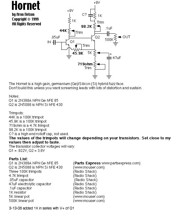
Hornet – OK! A germanium/silicon transistor hybrid Fuzz Face that screams! High gain, high sustain, ANGRY, yet can get bluesy when your guitar pot is turned down. Minimalistic design that can be “tuned” to perfection. Better watch out cause the Hornet will sting The Rocket!
The Hornet did not happen without the contributions of the usual netizens that help us so often. Alfonso Hermida, GFR, Gus Smalley, Jack Orman, R.G. and others. Thank you guys!From Jack Orman: Since the supply of 2N388A transistors have been depleted at Parts Express, I thought I’d post a few alternate devices
that they carry that can be used for F-F construction. Any of the below parts should be suitable and are less than $1
each. The last one is spec-ed a little weak but would likely be okay. The first one is a good sub for the 2N388A.Part No. Type Hfe Price
2N1306 NPN 100 $ .95
2N1308 NPN 150 $ .75
2N1309 PNP 150 $ .75
2N1373 PNP 60 $ .95 The NTE101 is another choice:http://www.nteinc.com/specs/100to199/NTE101.html
7/11/99 -Notes: Not much to this circuit; the trimpots allow you to really tune in and adjust the circuit. Please try the 2N388A transistors as they are dirt cheap (18 cents when bought in lots of 5 or more I think). The 2N5088s can be readily found through Mouser. The rest is pretty much Radio Shack or your local store. Convert to PNP transistors by changing the orientation of the lone 47uF electrolytic and reversing the battery polarity. (The battery AND 47uF cap POSITIVE to ground). Mods: The input cap is critical; for classic fat fuzz tones use 2.2uF to 10uF to larger! (you may consider socketing it – I did) The output cap is less critical; I have found that .1uF is fine for me. The .05uF that I use I have found to be very good because it changes the frequency response of my guitar the least. I have around the same bass as when the unit is bypassed. The trimpots allow you to really tune in the sound. Many shades of distortion will come out as you fool around and turn them. C? is a high end rolloff cap, you can put .001 to .01 to larger values and hear what it does (socket this cap). You can also put the usual 50K pot at the input BEFORE the input cap as described in the Technology of the Fuzz Face – (GEO) Excellent article about the Fuzz Face. You could also make the 1K resistor off of Q2’s collector a 47K, then make the 100K trim a 47K and tap the output off of the junction between the two. This will reduce your output level and make it a lot tamer.
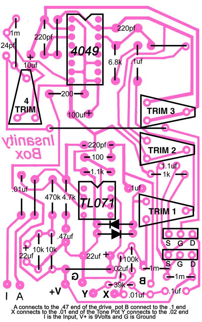
Insanity Box – OK! What can I say? I think it’s one of the best boxes I have built and one of the best ultra-hi-gain pedals I have heard. Thanks to Jack Orman for his wonderous circuit snippets, Frank Clarke for his work into CMOS circuits and all the rest that helped out. What is the Insanity Box? Just the pedal that delivers the high gain and sustain that I was looking for. I’ve been playing it for a while and I still love it! Aggressive, distorted and sustained, it’s got all the right stuff. Watch the G3 video when you play through it! With the Insanity Box I start a new concept called Circuit-Ware. A variation on shareware, I thought it up while playing a riff with the Insanity.Sound sample available.
11/26/99 – Built another one and it works fine. I believe the previous circuit I built on 11/10/96 had some type of bad voodoo in it. The schematic works and is fine. I didn’t need the bias pot for the 2nd one.11/20/99 Revision 6 online. More cleaning up and fixed a mistake.11/11/99 Revision 5a online. Jack cleaned up a few thing. Thanks!11/10/99 Revision 5 online. Optional bias pot to stop gating effect of CMOS if you have the gating problem when notes are decaying. You turn the pot until the gating is gone, measure the values of the pot from wiper to lugs and then put in fixed resistors. I have to point out that this is an advanced project. I built another one and it seemed pretty hard to build. So many things to keep track off. In addition, I had to put in the bias control – I just put one bias pot and connected a 1Meg resistor from each inverter input to the pot wiper. I ended with a 33K from 9V to the 1M resistors to inverter inputs, then a 56K resistor to ground. PCB Layout, Press and peel layout (TIF format) Thanks to John Catto! 11/5/99 Revision 4 online. The trim pot values are now listed. I measured them in circuit , with power off.11/3/99 Thanks to Jack Orman for pointing out errors and mods. The revised schematic (revision 2) is now online.Here is the pinout of the CD4049 chip.Here’s more on the CD4049 from Jack Orman.
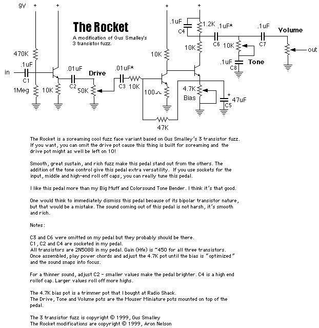
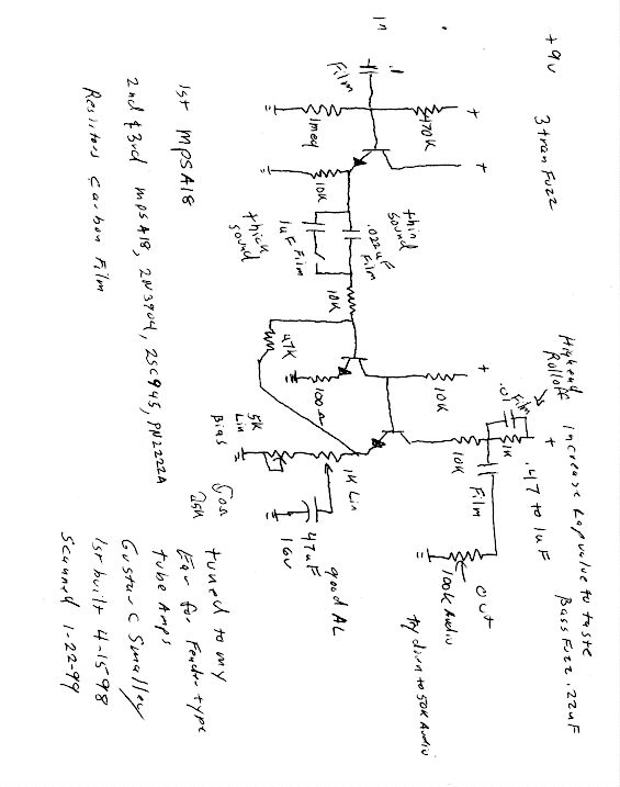
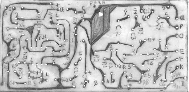
The Rocket, OK!a modification of Gus Smalley’s 3 Transistor Fuzz I came up with. Build the 3 Transistor Fuzz and this one too! Screaming, smooth and rich. I call it the Rocket because once you turn it on, you take off! Here’s a picture of the inside of The Rocket. Sample of The Rocket in RealAudio format. Transistor collector voltages: 8.4, 1.957, 3.199A
9/6/99 – I just built The Rocket using GEO’s PCB. It was easy to create and gives very professional results. A couple of mods as I played it through my Bassman and a 12″ speaker:Try substituting .047uF caps for both .01uF caps right after the buffer in the front. You can’t miss them, they are the only .01uF caps on the entire board. In addition, I really mellowed out the pedal by putting a .2uF cap (two .1uF caps in parallel) instead of the .1uF in the tone control. Remember that if you use caps larger than .1uF instead of the .01uF caps, you will have to increase the input cap value. Basically two .01uF caps will give you a midrange heavy tone with some bass cut – nice and slicing. Anything more will start giving you a smoother rounder tone and increase bass response.
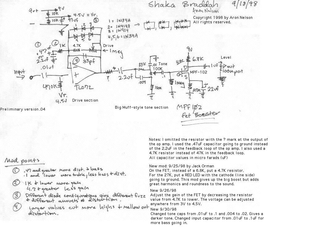
Shaka Braddah – OK! (pronounced Shock – Ah – Brah Dah) Preliminary version. IC based distortion with FET booster at end. When the drive knob is turned all the way down and level is up, you get a big boost. Goes from a hint of distortion to flat out heavy gain. The diode combination I chose produces a smooth nice distortion. I list a number of mods that you can make to the box. Put it on a proto board and mod it till it does what you want! Thanks to Jack Orman for helping with the design and the FET booster on the end!
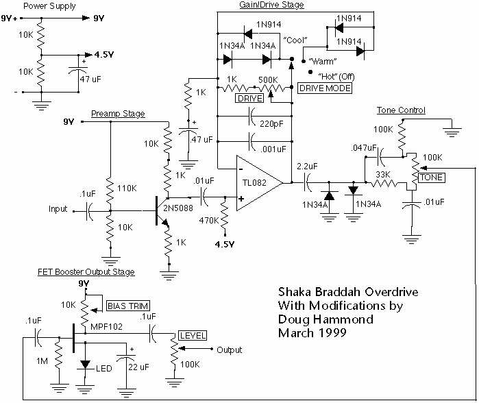
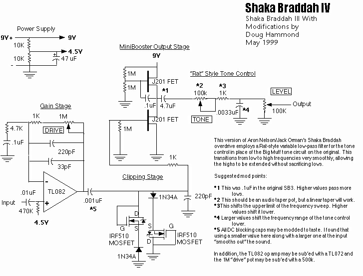
Shaka Braddah Mods by Doug Hammond. Check out the notes about the mods.
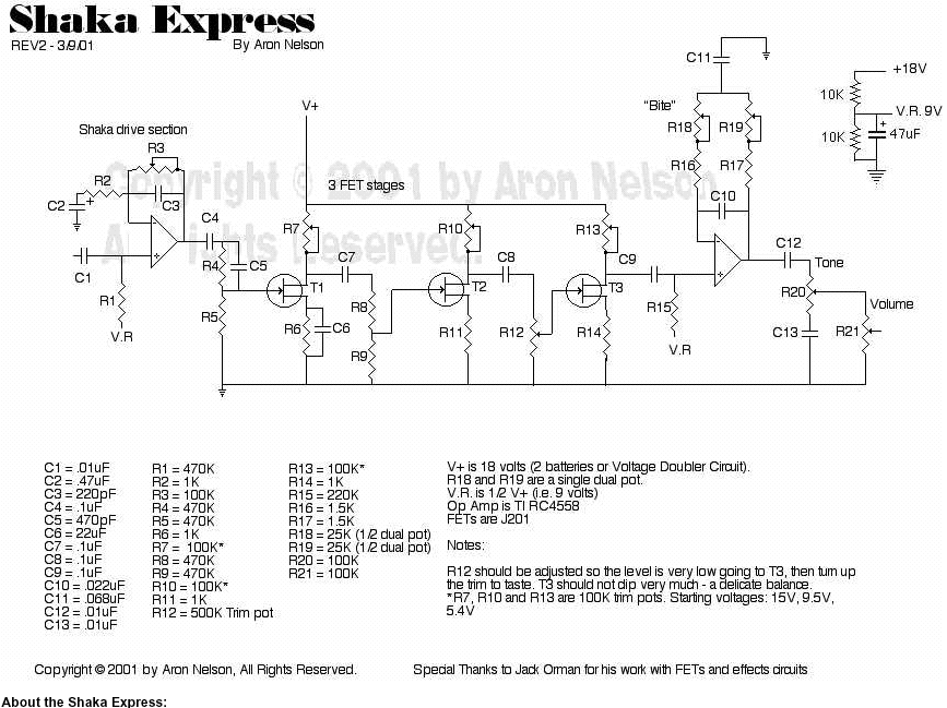
A hi-gain pedal for the guys that want to rock!. The Shaka Express represents the top of the line Shaka for hi-gain overdrive/distortion. The mid “bite” control gives your distortion “teeth” and the 3 FET stages make sure every nuance comes out loud and clear. Step on this pedal and take the lead. PCB and Layout available from GEO. Listen to a sample of the Shaka Express from sounds.ampage.org. JPEG available for people that are PDF challenged 🙂
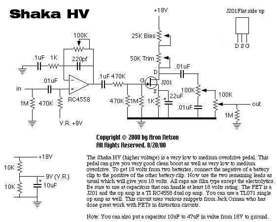
Shaka HV This one is for the guys that like more clean headroom and very little to medium overdrive. When the drive is turned all the way down, you can a great good clean boost. Runs on 18 volts (2 batteries) and has much less drive than my usual pedals! Easy to build and sounds good. HV = higher voltage. If you run it on 30 volts, then change the drive pot to a 500K.
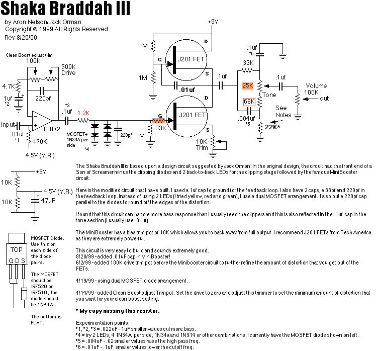
The goal of the Shaka Braddah line is to make a pedal that can have tremendous boost into an amp while preserving the tone of your equipment. The circuit should go from soft clipping all the way to heavy overdrive. I believe the Shaka Braddah III achieves this goal.
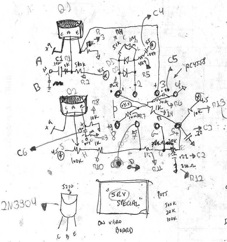
Shaka Braddah III – OK! A new version of the Shaka Braddah (based on a circuit by Jack Orman) that sounds very good. Creamy and smooth with some bite at lower drive settings. Smooth and warm at high drive settings with the FET booster smoothing out the diodes. Check it out! Sound sample available. Blake of Blakes Web Pages has a sound sample of his modded SB3.
The Shaka Braddah III was designed for you to be able to set the tone control (around 8-9 o’clock) to a neutral setting and get a booster/distortion that can make your guitar sound hotter and more vibrant. In addition, when the drive settings are turned up, it should sound like your amp is being cranked up. Thanks to John Greene for the idea of using MOSFETs as diodes.
PCB Available for the Shaka Braddah III from GEO
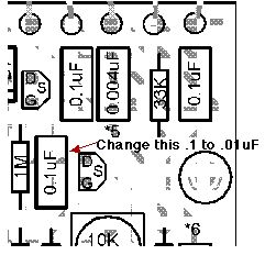
Note that the parts placement .pdf file incorrectly lists a TL074 for the TL072 IC and a 0.047 instead of .004 capacitor. Mods to try: 3 or more 1N34a diodes in series on each side of the clipping section. Each diode that you add will raise the clipping threshold and basically allow the Minibooster circuit to distort more before the clipping diodes start adding their sound. What this means is that you will hear more of the FETs before the diodes kick in. In a similar vein, I suppose that you could try 1N914 and 1N4148 diodes for their harsher sound and put then into the circuit. Since I socketed my clipping section, this will be easy for me to try soon. I have tried different ICs (RC4558 and LF353) and although the LF353 sounded different, I still like the sound of the TL072 fine. Try adding the “softness” or clipping threshold control noted in my Simple Mods page. 8/20/00 – Revised drawing. Fixed tone control, removed 100K trim etc…. 12/9/99 – Please try different op amps in the Shaka 3 circuit. They make a rather large difference and one that you can fool around with is the TS272CN (part number 511-TS272CN from Mouser). At 72 cents it’s a cheap, fun mod. It radically changes the sound of the pedal. The pedal becomes more midrange, distortion is radically different. More sustain at the expense of fidelity. Very interesting. 12/5/99 – If you like highs like I do, remove the 100K trimmer before the Minibooster and change the 10K trimmer on the source of the Minibooster to a 4.7K – that’s enough of a trimmer to reduce gain on the Minibooster circuit. The 100K trimmer loads down the circuit and reduces highs a bit.8/21/99 – There was an omission in the original schematic – my original Shaka III’s MiniBooster is also a treble booster. The new schematic reflects this change. With this simple change (1 cap), your Shaka III will be clearer, brighter and punchier. On R.G.’s board (which all of you should purchase), here is the capacitor you should change.7/4/99 – current consumption is ~5 mA, not bad.5/18/99 – Try different tone circuits with the Shaka III. Splice different types of tone circuits after the MiniBooster. Try the RAT tone control and others. I think you will find that the Shaka III circuit is extremely versatile and adapts to different tone controls. The pedal sounds very different when used with different tone circuits.5/9/99 – Notice that my Shaka III doesn’t have the 22K resistor going to ground in the tone control section. This probably explains why my pedal doesn’t get the scooped mids if this 22K resistor is there.4/18/99 – Wired 2 IRF520s as MOSFET diodes with a 1N34a diode attached to the source pin. This arrangement sounds extremely natural to me. Wire 2 of these and reverse them in polarity when attaching them to a circuit just like a diode pair.
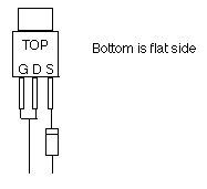
Diode is 1N34A, MOSFET is IRF510 or IRF520. Make 2 of these and then use them as diodes in the Shaka III.4/15/99 – Added a trimpot on the schematic which essentially allows you to control the amount of “clean boost” when the drive is turned all the way down. This trimpot allows you to make your “clean boost” really clean or kinda dirty – you know?4/11/99 – Tried 4 1N34a diodes on each side for a total of 8 diodes! The diode array tested at ~.822. Very nice… Even more nice dynamics, yet still has a smooth sound. I’m going to try some 1N914 and 1N4148 combinations for asymmetrical and other varieties of distortion. I realized I am able to mount the diodes onto sockets essentially creating a clipping “module”. I can plug these modules in anytime for different sounds.Check out Doug Hammond’s Shaka Braddah III mods which he calls the Shaka Braddah IV. I did like the sound of his mods. I find that the Rat circuit seems to produce less highs and this may work for amps which are bright.
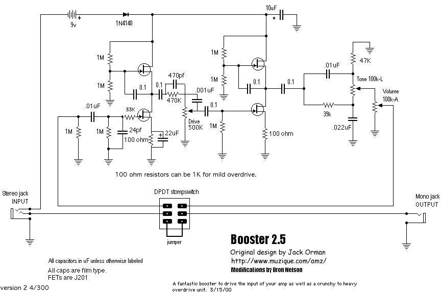
Booster 2.5 OK! The Booster 2.5 is the next generation of the Booster 2 designed by Jack Orman. I refined the circuit based on the refinements Jack put in his Mini-Tiubes pedal. The result is a stunning overdrive that has 90% of the wonderful tone of the Mini-Tubes with about 1/3 of the complexity. A great pedal, I am still enjoying mine. Also check out the Sweet Thing, which is the Booster 2.5+Doug Hammond’s mods. Another excellent variation; this one is on my pedal board. Coming soon: Boost switch, modified tone control…. possibly more… Sound sample available.
Hot Fuzz – My take on the Colorsound Tone Bender Professional Mark II with the Sweet Thing tone control. I’m still working on this one, so stay tuned. BTW: the “T” next to the pots mean use a trimmer. Sound sample available.
Apollo
Bell
- Flanger Part 1 and Part 2
Bixonic
- Expandora? see the hand drawn schematic
BossI would purchase all Boss pedals because most of them are very complicated and they are reasonably priced.
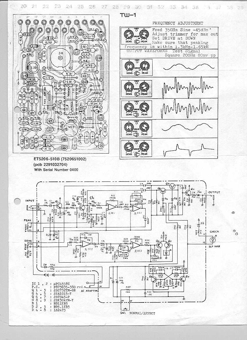
- Touch-Wah Wow. Tons of components in this one!
Colorsound (Sola Sound)
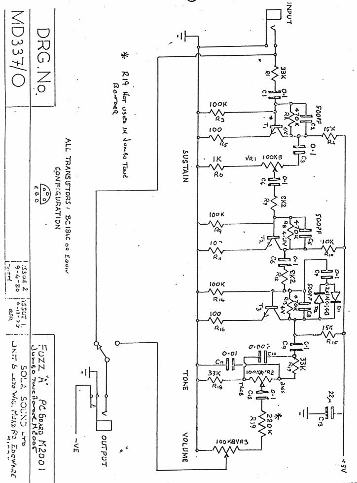
- Jumbo Tone Bender OK! Verified 8/9/98. Sounds initially like a transistorized Sonic 9 distortion (or rather the Sonic 9 is the IC version of this). Has a Big Muff/Sonic 9 single tone pot which goes from nasty slicing highs to full and round. Lots of gain. An interesting sound, It seems like I can still hear the original guitar sound in the output like it was mixed in. WaitAMinute! Look at the Big Muff schematic… Now look at the Jumbo Tone Bender… anything familiar? WaitAMinute! Look at the Big Muff schematic… Now look at the Jumbo Tone Bender… anything familiar?
Notes from John Catto:Today a friend of mine gave me a (not working – broken footswitch/one pot) Sola Sound Tone Bender. This is the three knob version built by many people on this board, including myself. There have always been some doubts about the schematic and now was my opportunity to clear this up once and for all!
The schematics posted by RG are pretty close, the only differences are..
1. ALL pots are 100k not 250k and no 2Mg (it appears the Yardbox is a closer clone than thought)
2. The resister from Q2 to earth is 3.3K not 33k
3. The capacitor that parallels the 3.3k resistor is 10uf on my unit not 22uf
4. On my unit there is a 220k resistor between the centre lug of the tone pot and the volume.The Transistors are all unmarked metal can, no doubt Germanium. The can has a narrow ridge around it about a sixth of the way up.One more thing, I’ve always believed that this design is the original design predating the more fuzzface like models with 2 knobs. This one however is dated inside 21 March 1974, so perhaps it is a later design after all or at least was still made that late. The case is a very slightly shallower version of the colorsound box, with silver paint and orange/black text.
Well there it is. I never thought I’d see one of these in the “flesh”
Tone Bender Professional Mark II.Check out the various Bender variations.
- SupaSustain – supposed to be very good!
Coron
- Distortion 10 – MXR knock-off. Thanks to Chris Winsemius.
Craig Anderton
Dale VanZile
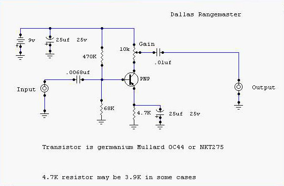
Dallas
- Rangemaster OK!
- 11-27-98 – Check out R.G. Keen’s GEO page for a very nice explanation of the Dallas Rangemaster and how to build your own!
Dan Armstrong
- Blue Clipper (Guitar Related Circuits) This schematic believed to have errors. Dan Armstrong said that MXR copied this circuit to make their Distortion+. He said they copied it line for line and added a tone control. Last I knew, the Distortion+ does not have a tone control.
Note:Jack Orman points out “the resistor from the inverting input to the 47uF cap is way too big: it should be 2k4 or even 240 ohms.”
- Green Ringer (GEO)The unmarked transistor is marked in my Green Ringer. It’s a Motorola MSD6150.
- Green Ringer (Guitar Related Circuits) This schematic believed to have errors
- Orange Squeezer (GEO) I have this compressor and it is great. Lee Ritenour, Jeff “Skunk” Baxter and others used this little “plug-in-the-jack” compressor with an on and off switch. I still use mine now and then when I want the “classic sound”.
DOD
- Compressor 280A (Guitar Related Circuits)
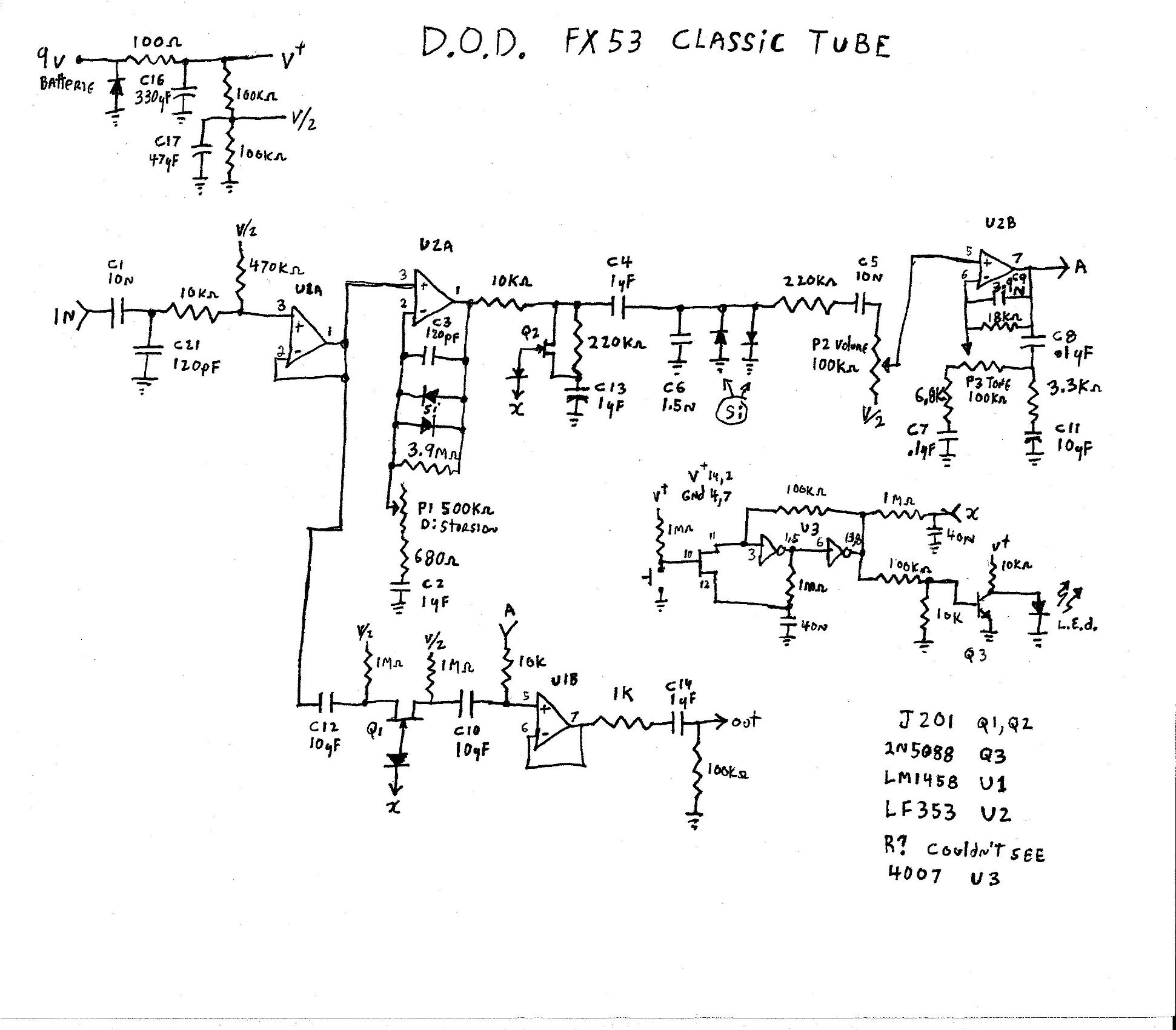
- FX53 Classic Tube – Thanks to Regent!
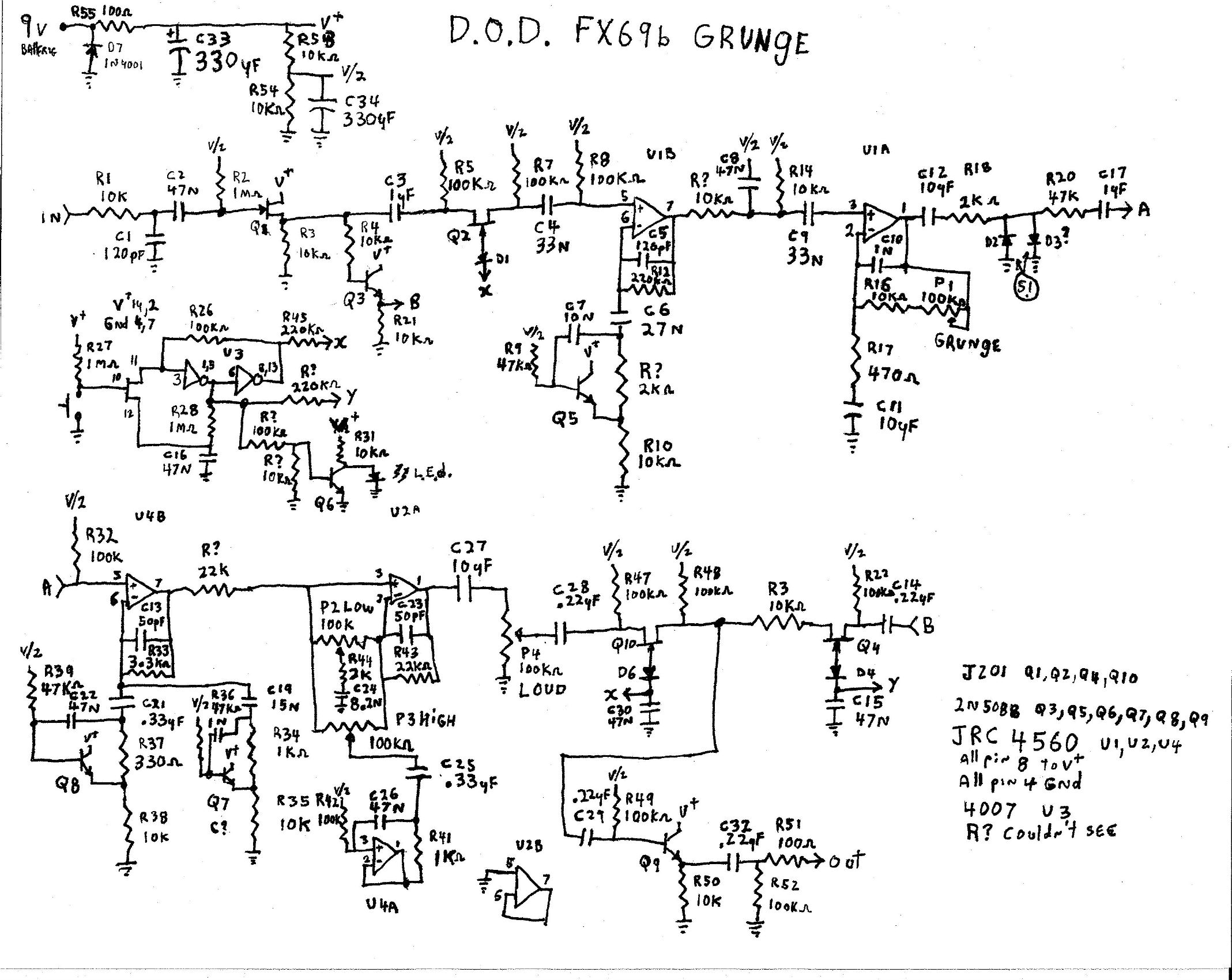
- FX69 Grunge – Thanks to Regent!
- FX75 Flanger (Guitar Related Circuits)
- Overdrive 250 (Guitar Related Circuits) OK! Very close in design to the MXR Distortion+.
- Compressor/Limiter 525 (AMZ)
- Wah/Filter 545 (AMZ)
- Chorus 565 (AMZ)
- Analog Delay 585 (AMZ)
- Phasor 595 (AMZ)
- Compressor 825 (AMZ)
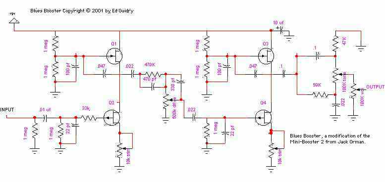
Ed Guidry
- Blues Booster – sounds great!
EQ Circuits
- 4bandeq.ps.Z (Guitar Related Circuits)
- Signal Brightener (Guitar Related Circuits)
- 10 Band EQ (Guitar Related Circuits)
- Tone Booster (Guitar Related Circuits)
- Tone Control Circuits (Guitar Related Circuits)
Electro-Harmonix
- The EH Man’s site is THE place for EH info. Check out the COOL articles.
- Attack Decay Blum is asking for help on this:The biggest problems for me are :- MN 3007, 4047,4066 and 4013 pins
- – LM 311 out (I suppose it`s LM 311?) If you have ideas, please post on the forum.
- Axis – same as Guild 2 knob Foxey lady!
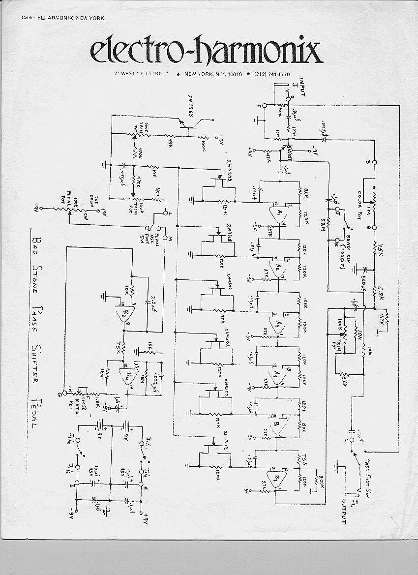
- Badstone Thanks Steve Giles!
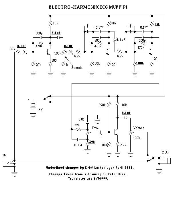
- Big Muff (Transistor)(Guitar Related Circuits) OK! I used 1N914 Silicon and 1N34 Germanium diodes in parallel with high gain 2N5088 transistors in my Big Muff. This schematic probably missing 100K resistor from base to ground on the 3rd transistor stage. The 3rd stage should be identical the previous stage I believe. Check out the Muffler from John G.
- Triangle version Big Muff. A modified R.G. (Geofex) schematic of a Triangle era-Big Muff. Possible mods and notes: You can try NTE123AP, which is pretty much 2N2222 transistors. Try lower hFE transistors – like 150-250 instead of the usual 400+. Ed Rembold suggests Q1 base to ground 47K.
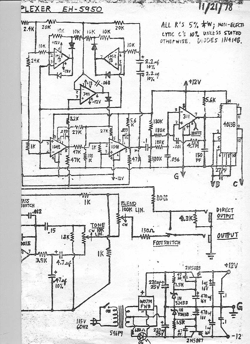
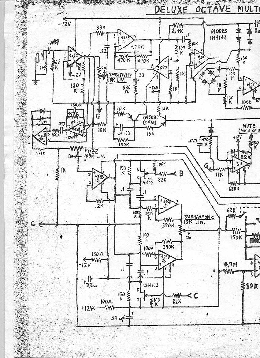
- Deluxe Octave Multiplexer A and B
- Doctor Q – hard to read. I do not recommend this circuit. About 30% of people have gotten it to work but I think it’s problematic and irritating, try the Dr. Quack instead.
- Simple Deluxe Memory Man reissue mods that can be done. OK!
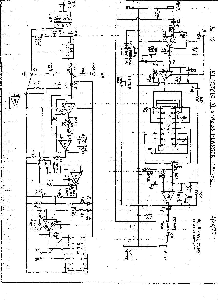
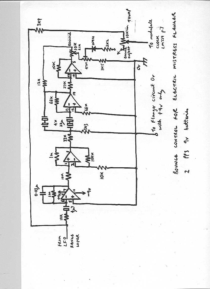
- Electric Mistress Flanger Thanks Steve Giles! Also check out his bounce mod.
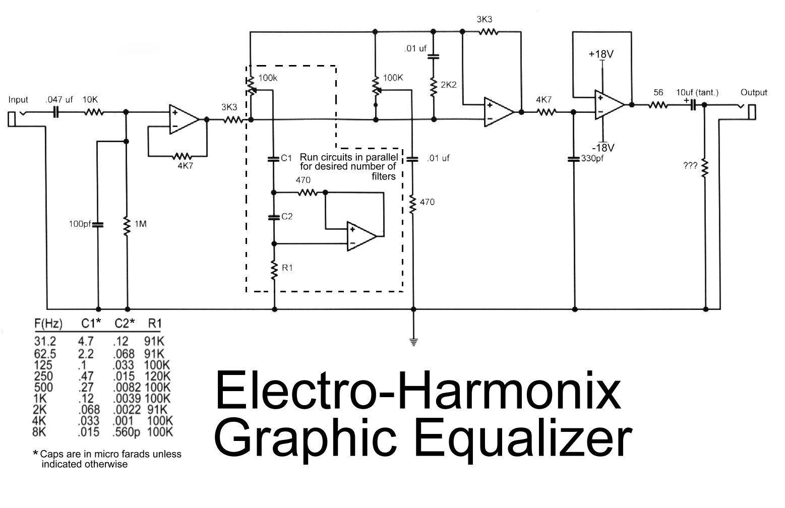
- Graphic EQ Thanks to Brad Fajardo!
- Graphic EQ (GEO)
- LBP and other Boosters (Guitar Related Circuits) I used to buy these LPB-1 boosters all the time. They were so useful for driving different things. Make one in about 10 minutes.
- Little Big Muff – I remember having one of these. I wonder where it went? Really nice schematic by Tobias!
- Muff Fuzz (Guitar Related Circuits)
- Small Stone (Guitar Related Circuits) This schematic believed to have errors, read below. A classic. I still have mine. Notes: According to Jack Orman, “Pin 2 is marked as the non-inverting input when it is actually the inverting input…. it’s marked this way consistently on the schematic. You have to feedback from the output to the inverting input (except for a Schmitt trigger). I verified this in the RCA data sheet for the CA3094 – pin 2 is inverting and pin 3 is non-inverting”
- Soul Preacher (Guitar Related Circuits) I never really liked this thing. Mine had a problem where it would amplify all the noise and then clamp down when I picked a note. While it clamped, it took about 3 to 4 seconds to recover.
- Space Drum – I still have one of these somewhere! Prototype1, Prototype2 Thanks Steve Giles!
Elektor
- Variable Fuzz – this looks very interesting.
Eventide
- Fender Blender (Guitar Related Circuits)
- Blender (GEO)-Wild sucker. Some octaving, but mainly “destroy the sound “distortion.
Foxx
GCS/Gus Smalley The following are circuits that are variants of existing circuits but with hand-picked substitution values/parts by Gus Smalley. Please try these…
- Another Sick Fuzz This looks easy to build!
- BJTBoost – Booster circuit using Si transistors.
- 3 Transistor Fuzz OK! Build this cool variation of a Fuzz Face, it’s great! Check out Guilherme’s extension of the 3 transistor fuzz. Schematic and Layout and notes.
- GCS Fuzz F. OK!
- GCS JH2 Fuzz Mod.
- GCS Overdrive OK!
- GCS Ritefuzz
- GCS MFUZZ – A modified Muff Fuzz. Sample of the MFUZZ in RealAudio format. OK! Gus recommends an LF353 for the dual op amp. “The circled options are to make itsound more like a Big Muff high and low end rolloffs”. “Whenyou disconnect the feedback pot and leave just the 1n4148 diodes it goesinto what I call sick mode Think Edges U2 broken fuzz sound on POP tracks 1 and 2.It also sounds very good in the loop of a lovetone meatball effect”. “I use100k audio pot on the output of effects because of the way the drive ofthe IC and the pot interact with the 1st tube in a tube amp it has asmall tone effect”.My notes: I think this is an easy-to-build single IC chip distortion/fuzz. Experiment with the diodes (try LEDs, germanium diodes et…). Adjust the input and output caps to your liking.
- MBB Fuzz based on Bee Baa Fuzztone. Looks like it might be good for bass too.
- MOSFET Overdrive – hmmm…. looks cool, I will have to try this one.
- NPN Boost – Gus’ answer to the myriad boosters out there. Si too!
- NPN-Drive – check it out!
- Octave Up Sick Box A wild and crazy octave up sick box. Mine worked a little, but I think there might be some problems with this circuit.
- Simple Fuzz – simple and fun.
- Simple Octave Up – uses a transformer.
Gretsch
Howie’s Effects
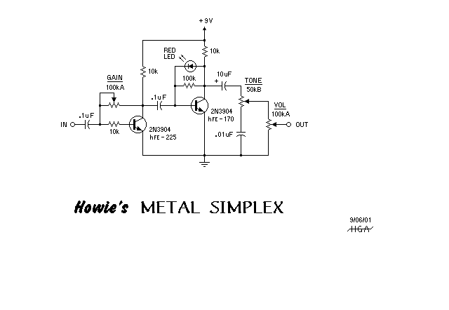
- Howie’s Metal Simplex – Howie’s metal pedal – a very simple design. Check it out!
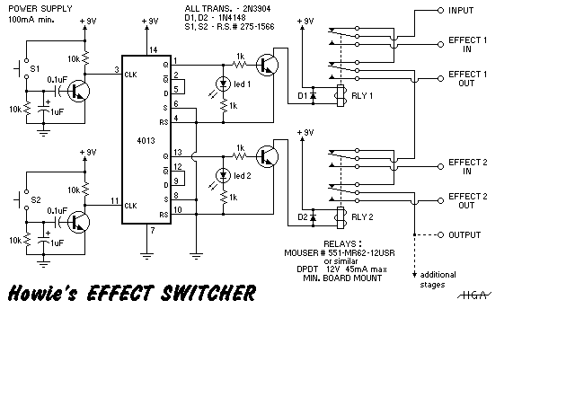
- Howie’s Effects Switcher – looks very useful.
Ibanez/Maxxon
- AD100 Analog Delay Nice drawing!
- MT-10 – Mostortion.
- Sonic Distortion (AMZ) OK! Lots of distortion, from semi-clean to very distorted. Cool tone knob. I used an RC4558 in place of the TL072 here. This pedal is good for heavier distortion settings. Imagine RAT and Big Muff thrown together.
- Super Tube Screamer – Someone was selling these for $1000 each.
- Tube Screamers (GEO) – Check out The technology of the Tube Screamer.
- Check out Bill Bergman’s nice TS layout (TIFF file).
What is the Tubo Tube Screamer? From Dai Hirokawa: “TS9″(Normal) mode(for comparison): .047uF mylar w/two small signal Si diodes
“+” mode: 0.22uF polarized electrolytic w/four small signal Si diodes–two for the top of the waveform, two for bottom (these look the same as the ones used for the normal setting)
“Hot” mode: 1uF polarized electrolytic w/pair of LEDs(w/a 470k in parallel w/the LEDs)
“Turbo” mode: 2.2uF polarized electrolytic w/no diodes(seemed odd but it does look open)
-the 4.7k and 51k are unchanged for all modes
- TS-5 – Thanks George Ong!
Interfax
- Harmonic Percolator – OK! Thanks to Alfonso Hermida!! Updated 7/10/01
Jack Orman /AMZOrder Jack’s CD for all of his cool projects. Lots of the coolest pedals have been created with snippets and circuits of Jack Orman’s work. Check out his creations!
Jay Doyle
- FET Punch – The FET punch uses readily available parts to create a versatile overdrive.
- Shaka Smooth – A smooth addition to the Shaka Line! PDF file.
Joe Davisson Joe is on a roll and is devising new pedals for us to try!
Joe Gagan
- Skyripper Fuzz – soon to be famous FUZZ! Ridiculous sounds, wild, wacky, THD to da max, maybe the ultimate fuzz?
John Hollis – Cool Website too!
- EasyVibe
- Zombie Chorus
- Crash Sync I have always wanted this….
- OmniDrive –no more pedals after this? 🙂
- Titan Boost and Titan Octave
- Phantom Wah
Jordan
- Bosstone OK! I believe this is the correct circuit. Lotsa FUZZ. This circuit is not very touch sensitive. More of an in your face type of fuzz. This thing has so much output it will blow most amps sky high! Lotsa gain!